Saab V4 Clutch Replacement
The clutch release bearing had been grumbling for some time, so the decision was taken to replace the whole clutch assembly.
In this process the gearbox was left in the car and just the engine removed to access the clutch.
The clutch release bearing had been grumbling for some time, so the decision was taken to replace the whole clutch assembly.
In this process the gearbox was left in the car and just the engine removed to access the clutch.
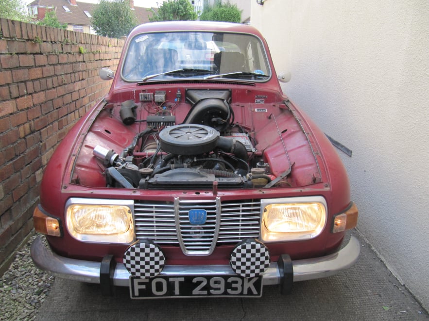
The bonnet was remove by pulling out the 'R' clips on each hinge, unplugging the washer pipe and lifting it clear.
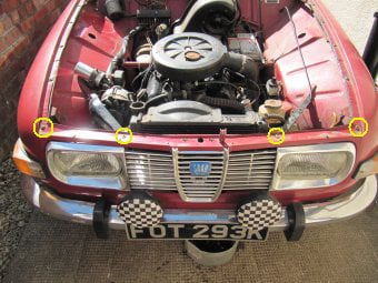
The front panel was removed by undoing the four screws shown above.
The bonnet release cable was disconnected and the headlights unplugged.
The coolant by undoing the drain tap on the bottom of the radiator (11mm). The battery was also disconnected (13mm).
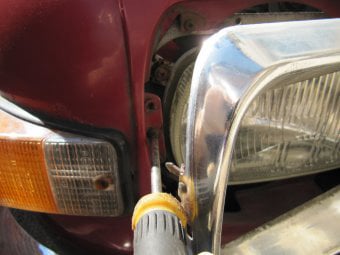
Older cars with the chrome grill have a clamp on each end which can be accessed behind the headlight trim. This can just be loosened and the clamp swung clear.
Newer cars with the plastic grill have a simpler self-tapping screw in place of this arrangement.
The radiator was removed by undoing top and bottom hoses and the two lower securing bolts (and on this car unplugging the electric fan). It was lifted clear with expansion tank in situ.
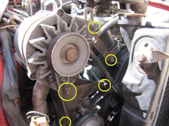
The more ancillaries removed from the engine, the easier it is to maneuver and so the alternator and mounting bracket were removed by undoing the 13mm bolts shown.
The air box was also removed to make way for the hoist.
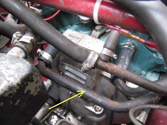
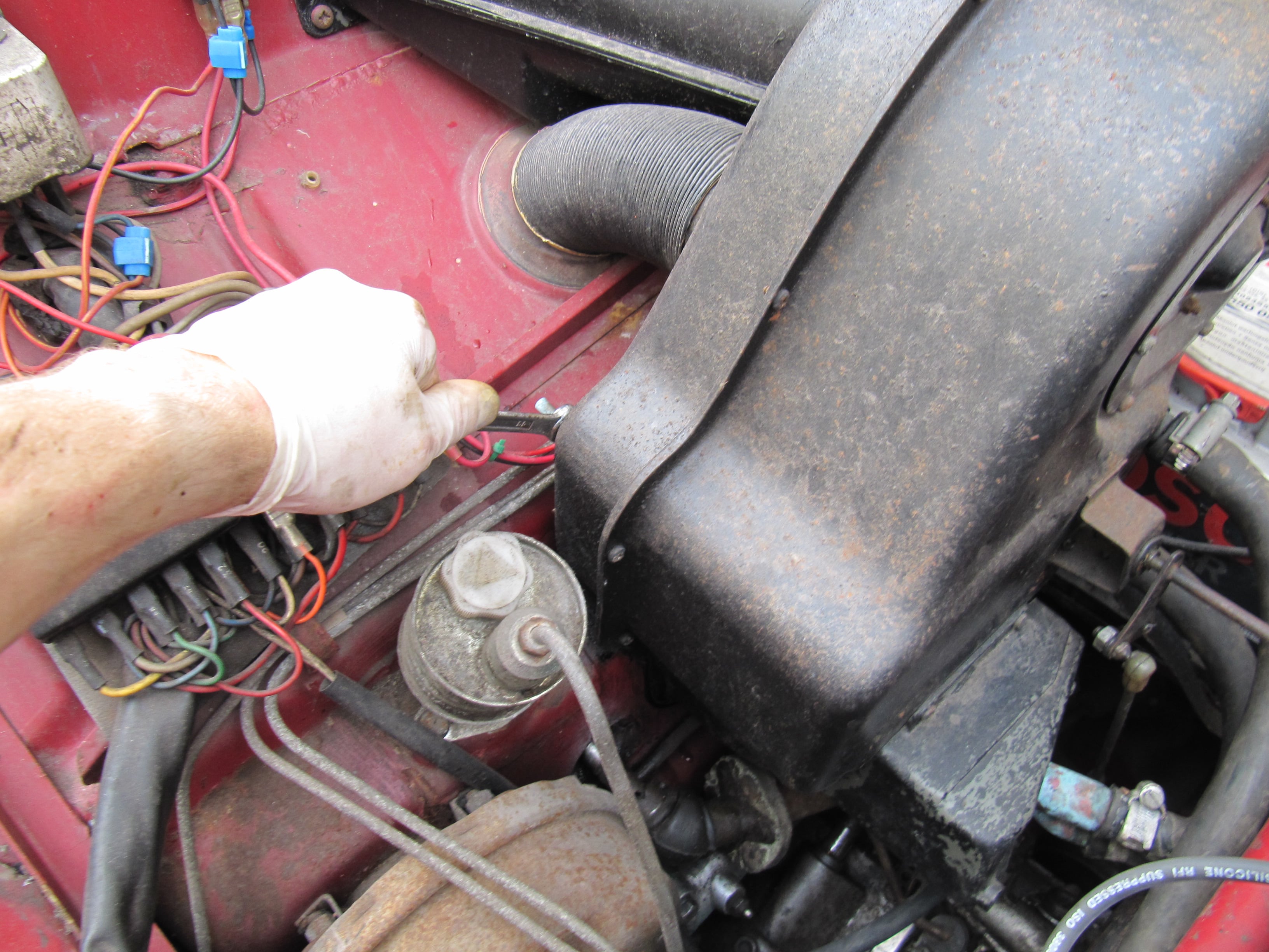
Other items to be disconnected were the throttle linkage, choke cable, brake vacuum hose, exhausts, heater hoses, coil leads, fuel pipe and the coolant pipe which runs round the back of the engine (arrowed).
This pipe is a wrestle to remove as three hose connections have to be separated at once, but it needs to come out to allow the engine and gearbox to slide apart.
The engine and gearbox steady bars were removed.
The top two bell housing bolts were removed and the two front engine mounts undone
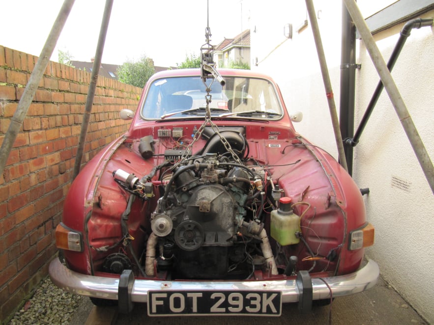
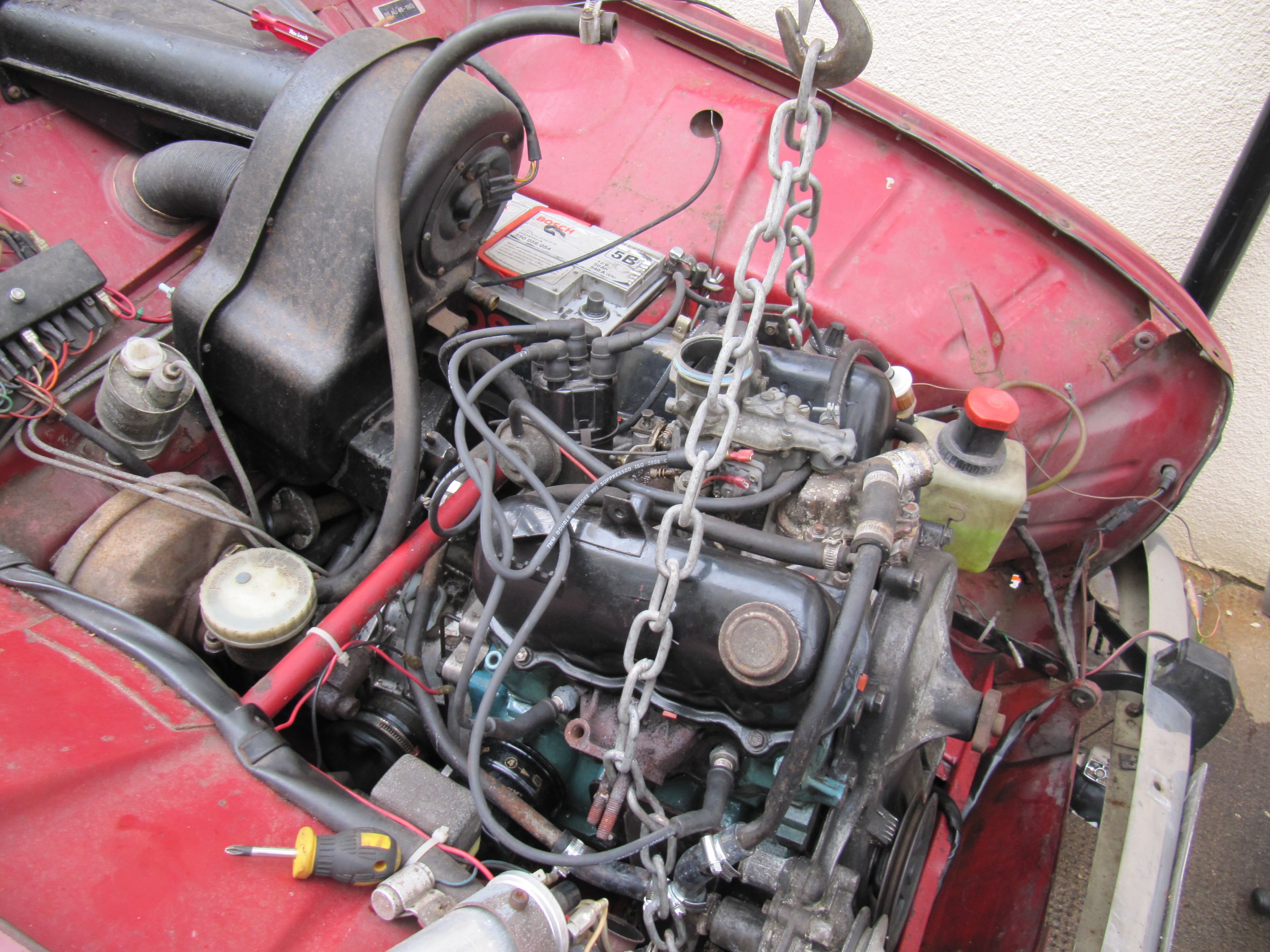
The engine hoist was connected to the exhaust studs via a welded link chain.
The engine was carefully raised to sit at and angle with the sump clear of the front valance.
The exhaust can be difficult to disconnect here, but with some gentle lifting and moving of the engine from side to side it should come clear.
With the engine held in this position and propped up on some chocks, the starter motor was removed using a 14mm socket on a long extension bar.
The gearbox was now supported by pushing some wooden spacers under the front edge of the bellhousing. Total height of these spacers was 2.5"
Then the remaining bell housing bolts were undone using a 17mm spanner.
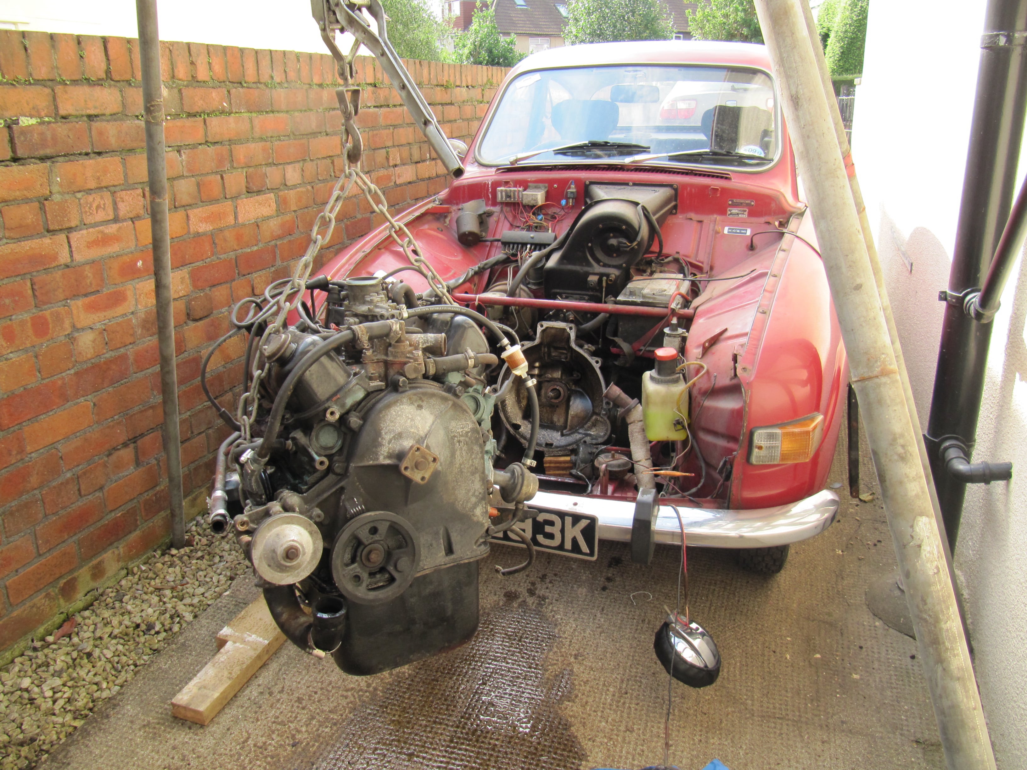
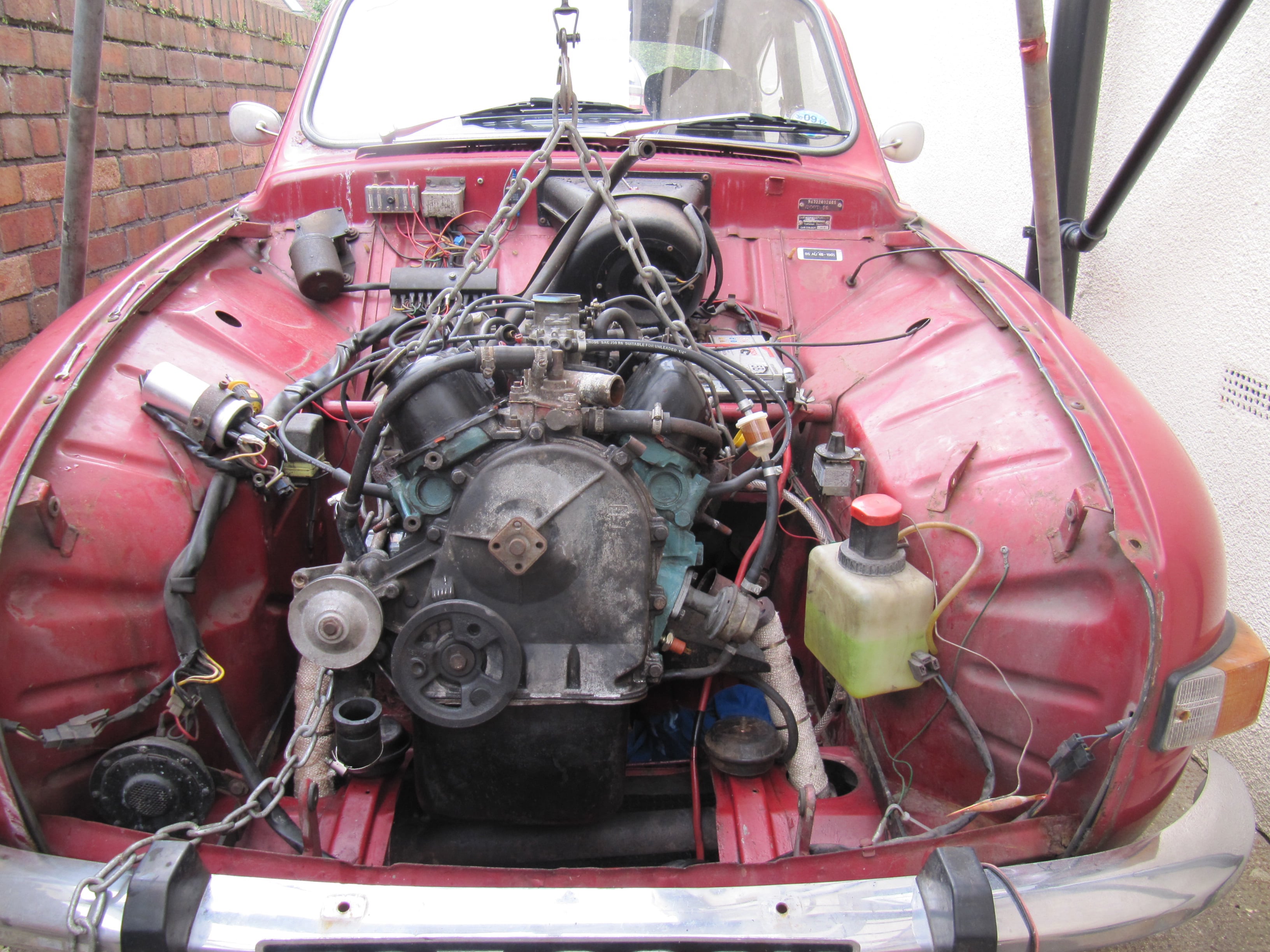
The engine could now be pulled forward out of the engine bay.
The gearbox was left supported by the wooden spacers under the front edge of the bellhousing.
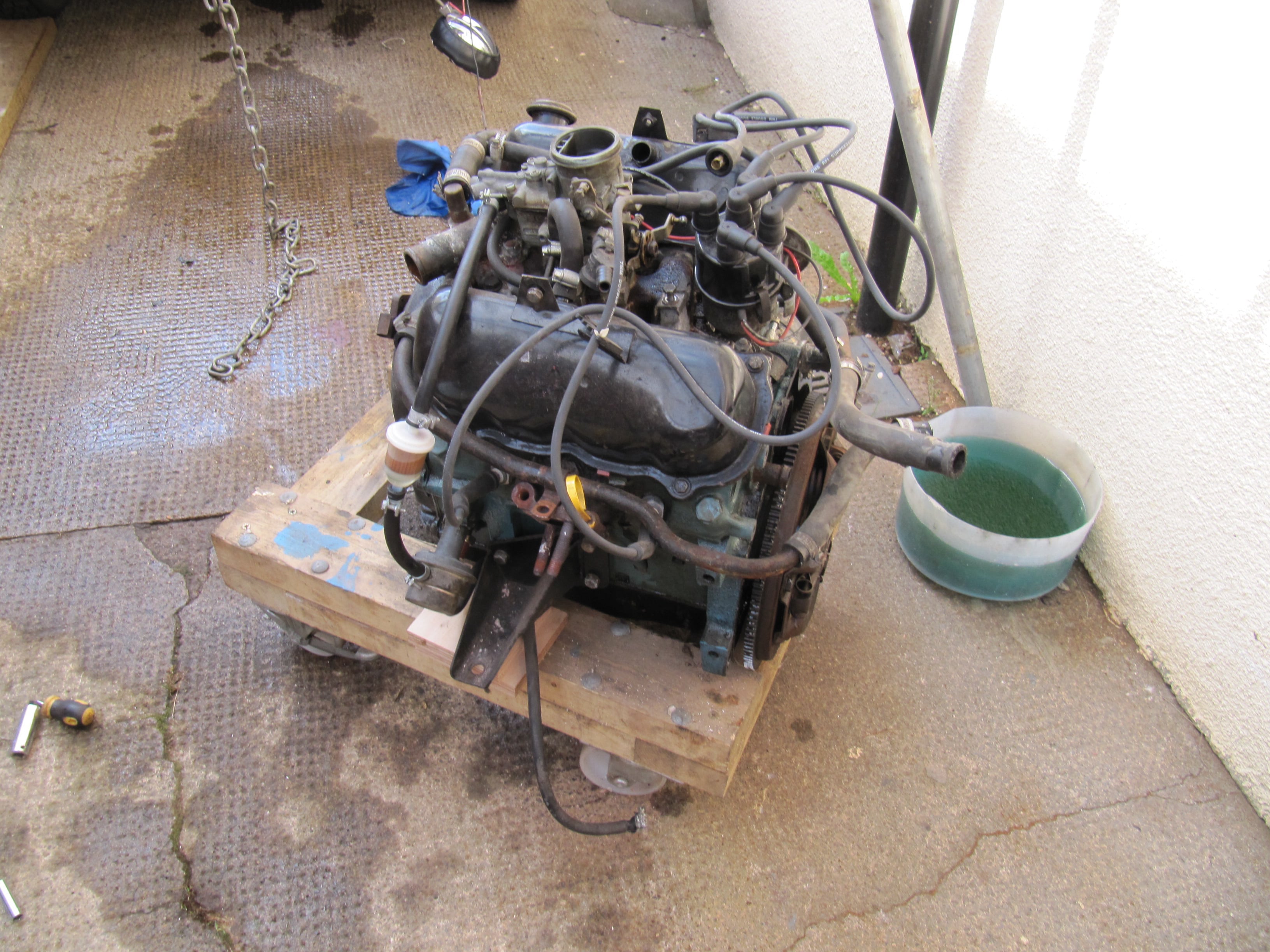
The engine was lowered onto a wooden frame.
The old grumbling bearing could now be pulled out, by removing the top and bottom 'R' clips.
To remove the old clutch plates the six bolts holding the clutch to the flywheel were removed. To stop the flywheel turning a ratchet strap was looped over the engine body to pull the flywheel teeth into the wooden frame of the dolly.
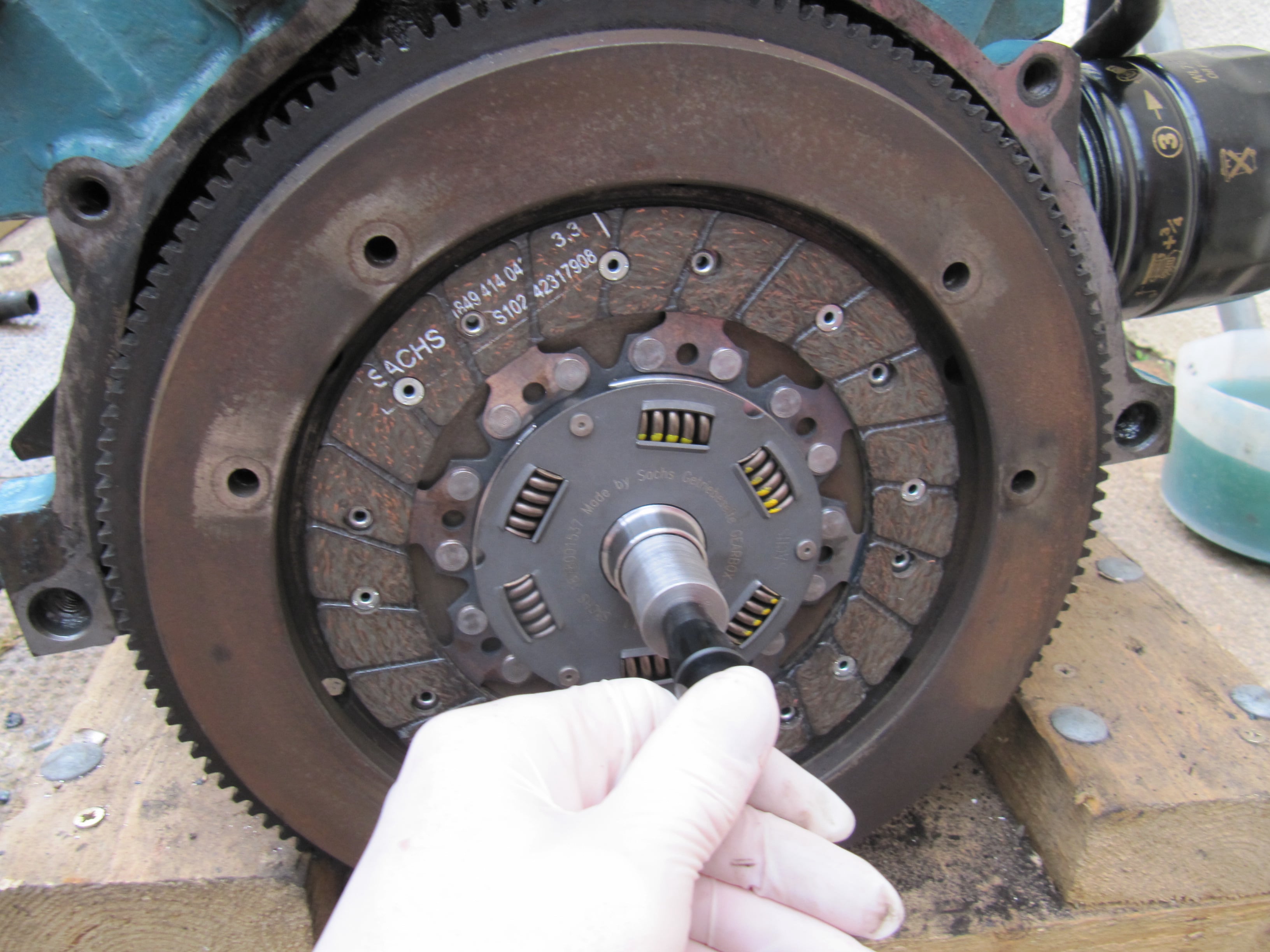
The new friction plate was placed on the flywheel (note the orientation marked on it) and a home-made alignment tool turned from a scrap piece of bar, was used to centre it.
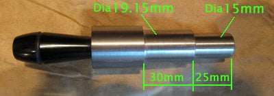
Critical dimensions for the centring tool are shown above.
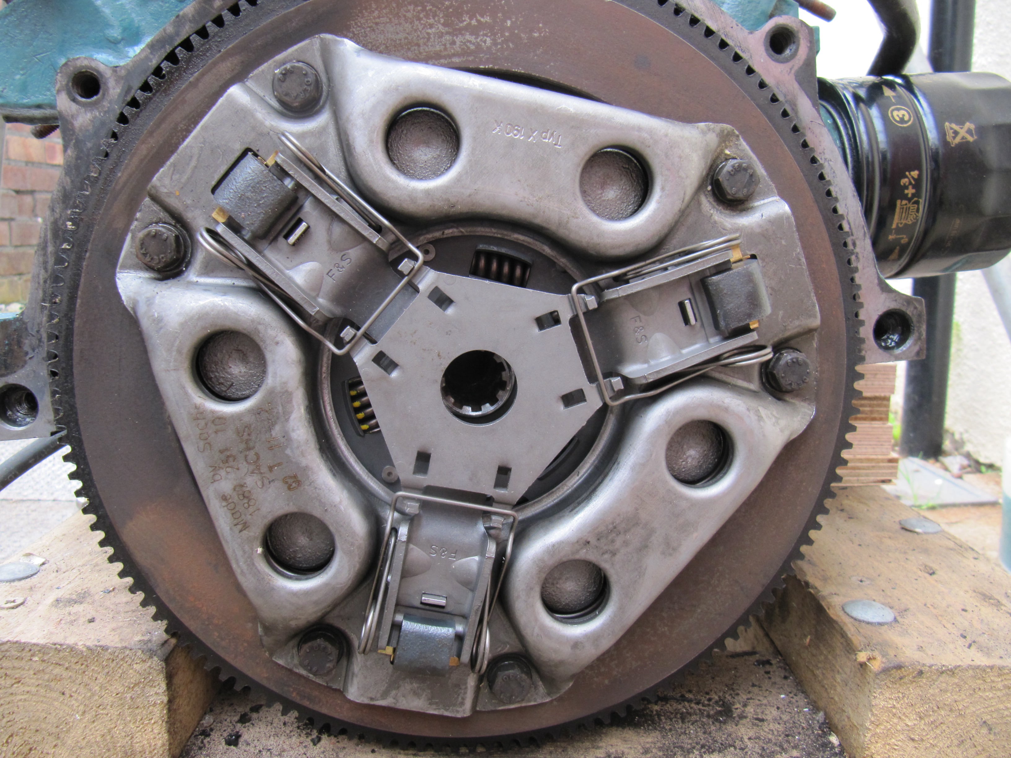
With the clutch friction plate centred the pressure plate was bolted into place tightening in sequence, the flywheel being held as before.
Then the engine was lifted back up and presented to the gearbox.
Getting the gearbox shaft to slide through the clutch plate requires care so as not to bend the gearbox shaft.
Once the end of the gearbox shaft had entered the clutch the engine was lifted or lowered to get the angle correct. The car was put into first gear and rocked to rotate the shaft until it all dropped into place.
The bell housing bolts were replaced and tightened. Before lowering the engine, it was propped up, and the starter replaced.
With the gearbox chocks removed, the major obstacle in lowering the engine was the exhaust. Careful engine positioning and easing of the exhaust past the manifold studs was needed to get it into place.
At this point the clutch was checked so that with the car in gear it wouldn't move until the pedal was pushed and then it would roll.
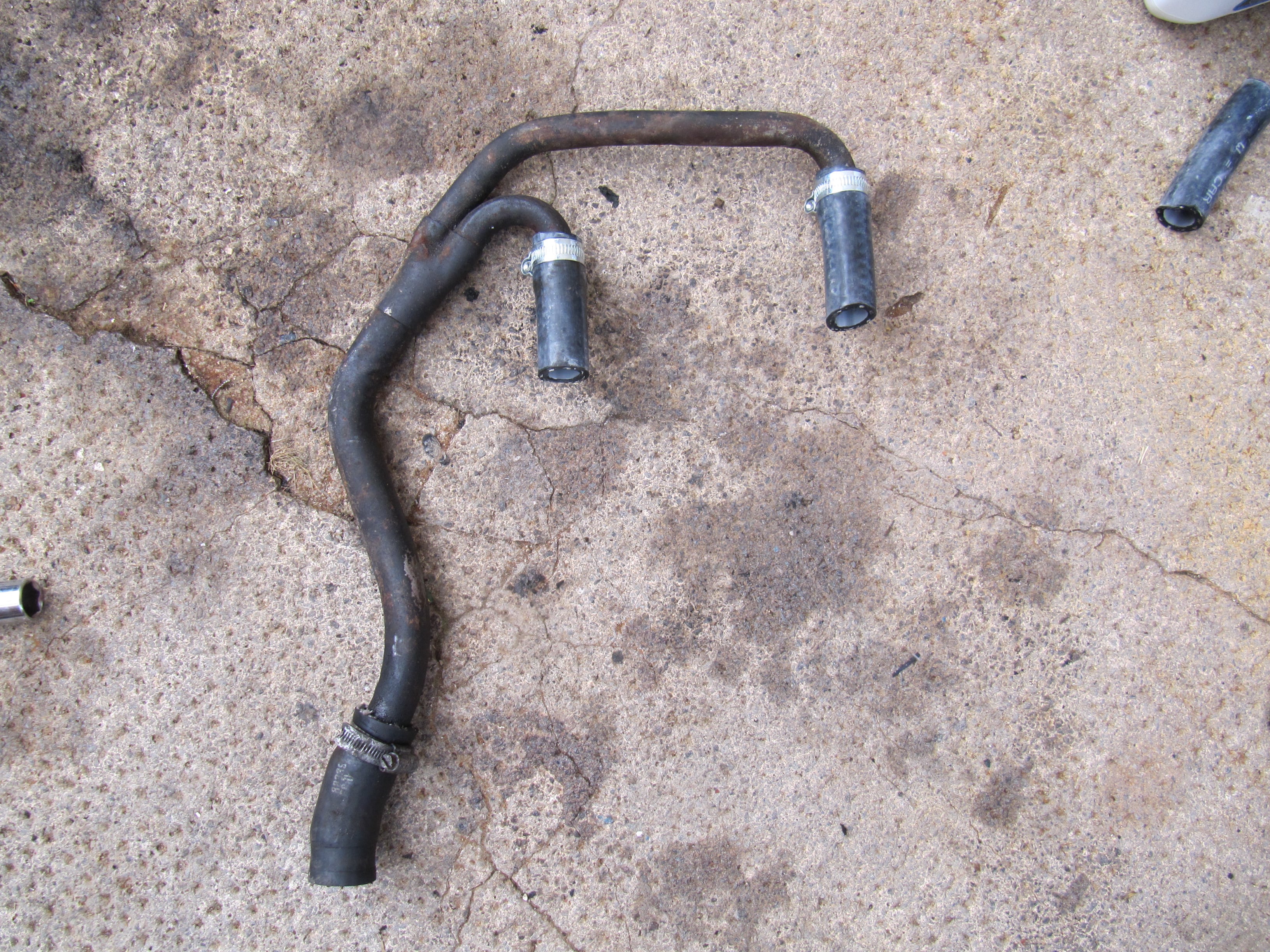
All the wires, cables and hoses were reconnected. The connecting pipe shown here is always a fiddle to fit, trying to get all three hoses to engage at once and slide into place. Liquid soap and perseverance was needed.
The alternator was replaced and the radiator put back, taking care to use the short bolts so that they didn't puncture the radiator side tanks.
The engine and expansion tank were filled up with coolant, and the engine started.
The engine was run up to normal operating temperature. With the heater set to hot, the system was bled using the screw (11mm) on the heater matrix and then topped up.
The front panel and bonnet were replaced to complete the job.
The clutch was adjusted so that it had the most travel available to make changing gear easier, but without the release bearing contacting the pressure plate all the time.
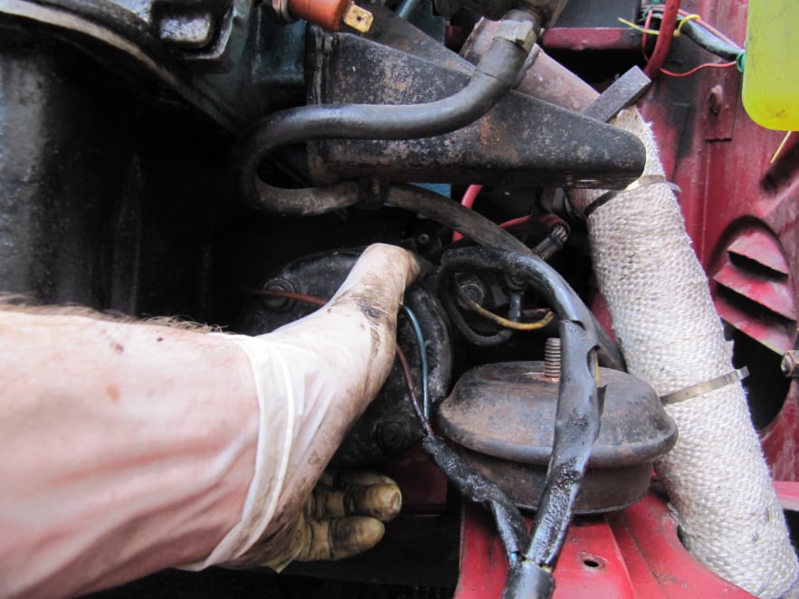
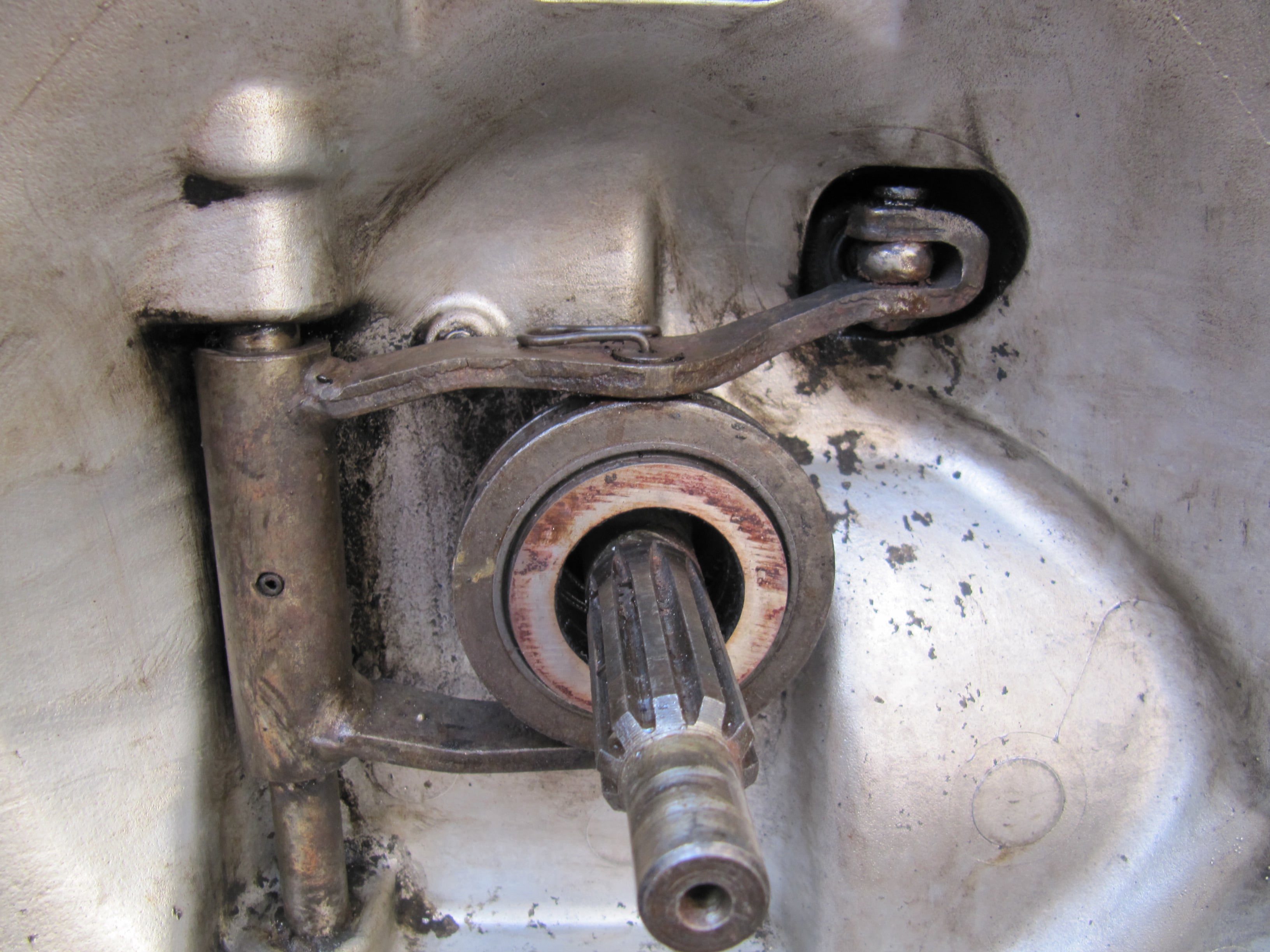
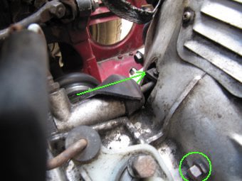
This image shows the end of the clutch push rod which can be viewed by peeling back the dust cover.
Pushing hard in the direction shown will allow the free play at the slave cylinder to be checked. There must be movement available between the resting position of the push rod and the release bearing touching the clutch, however this movement can be minimal.
It is important that the release bearing is not turning all the time, as this could cause it to fail early. With the engine running is it easy to feel when the bearing contacts the clutch.
The resting position of the clutch arm can be adjusted using the screw circled. Once the free play is set, the lock nut can be used to hold the adjuster in place.

AI Website Creator