Mobirise Website Builder

Saab V4 Front Ball Joint Replacement

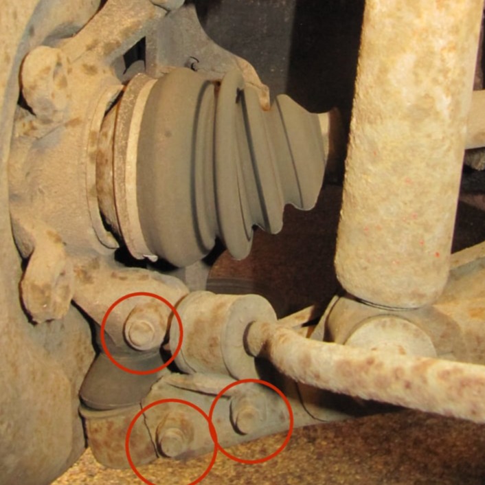
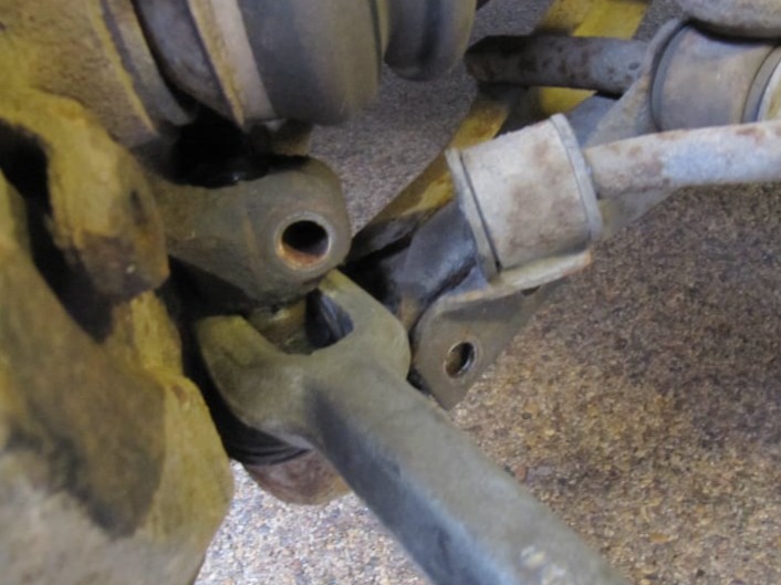
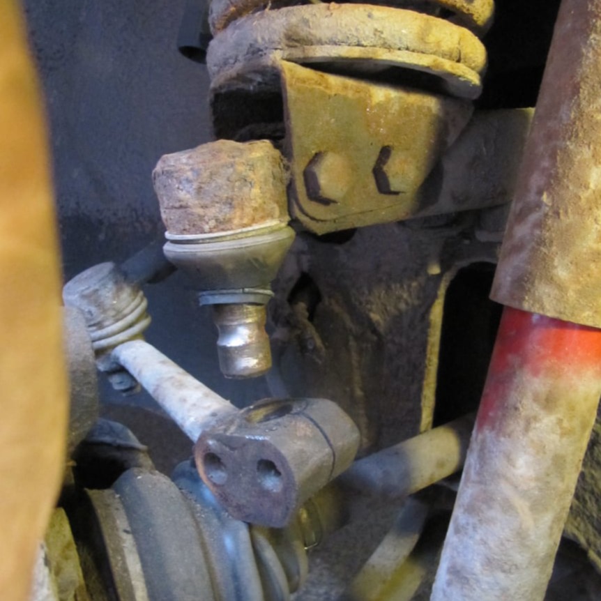
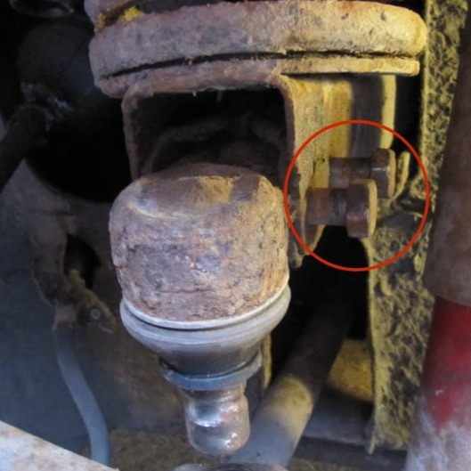
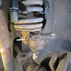
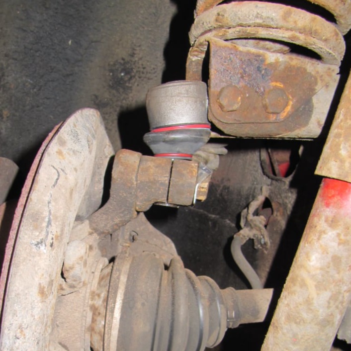
This page details the replacement of the front ball joints on the Saab V4.
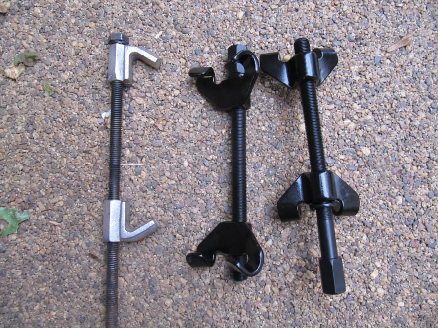
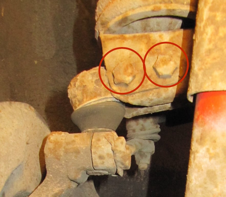
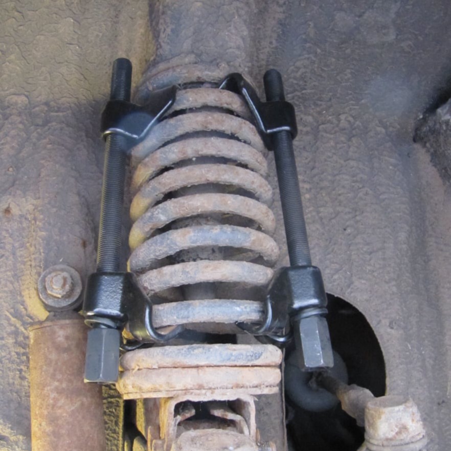
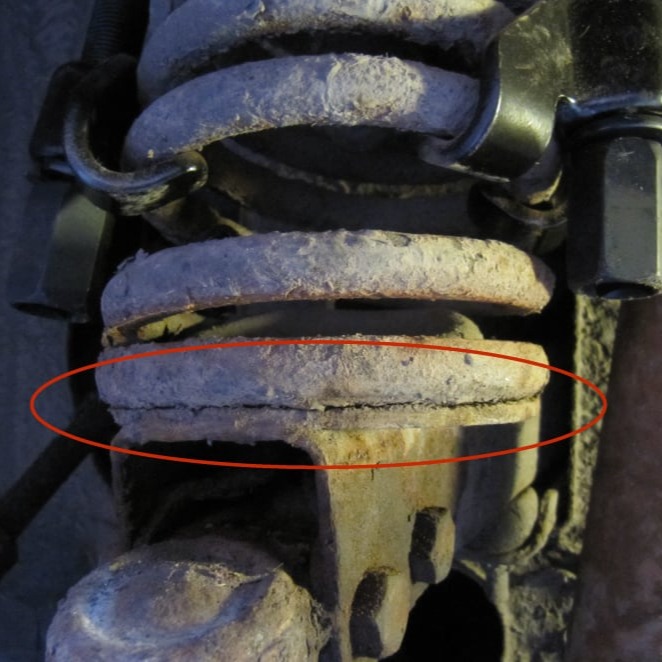
Be aware that removing the top ball joint also releases the main suspension spring seat, which contains a serious amount of energy, even with the suspension fully relaxed.
Proper precautions must be taken to prevent injury.

Mobirise Website Builder

It is worth re-iterating how hazardous suspension springs can be. If you are at all uncertain about this then you should not attempt the job. However with a decent spring compressor and some caution it can be done safely.
With this in mind the spring compressors used for the job were basic, but strong units, as shown on the right here. The style on the left are rather weak and can bend during operation, the single claw can also twist and come adrift from the spring coils. The double hook versions are stronger and more secure.

Mobirise Website Builder

To start the road wheel was removed in the normal way and the car placed on an axle stand. 
The bottom joint was replaced first by slackening the three screws shown above.

Mobirise Website Builder

Then a forked ball joint splitter was hammered into the join between ball joint and the steering knuckle to separate the parts.

Mobirise Website Builder

The top ball joint was replaced using a similar procedure, but noting that the two wishbone bolts also held the main spring in place.

Therefore any hammering or drifting of the old ball joint was done with these two bolts still in place on the wishbone.

Mobirise Website Builder

The spring was compressed by lifting the car on the jack and placing an axle stand under the end of the lower wishbone. Lowering the car then compressed the spring.
In this position the spring compressors were fitted. Lifting the car then allowed the compressors to take the strain and could be done whilst keeping some distance from the spring.

Mobirise Website Builder

With the car supported on axle stands once again, the two pinch bolts were removed from the steering arm.

Then the forked ball joint splitter was used again, to separate the upper wishbone from the steering knuckle.

Mobirise Website Builder

The spring compressors were then tightened until a gap was seen between the bottom of the spring and the spring cup, indicating that the spring tension was no longer pushing on the spring cup .

Mobirise Website Builder

The nuts were removed from the ball joint securing bolts which were then checked for free spinning, indicating that there was monimal load from the spring pressing on them. 

Mobirise Website Builder

One bolt was removed and a screwdriver inserted before removing the second bolt. Then the ball joint could be wriggled partly free, before swapping the screwdriver to the other hole and extracting the ball joint completely.

Mobirise Website Builder

The new ball joint was placed in the wishbone and the "safety screwdriver" re-inserted before inserting first one securing bolt and then the other.

Mobirise Website Builder

The steering arm was re-attached using the original bolts but with some new securing plates made from 0.8mm steel plate.

WYSIWYG HTML Editor