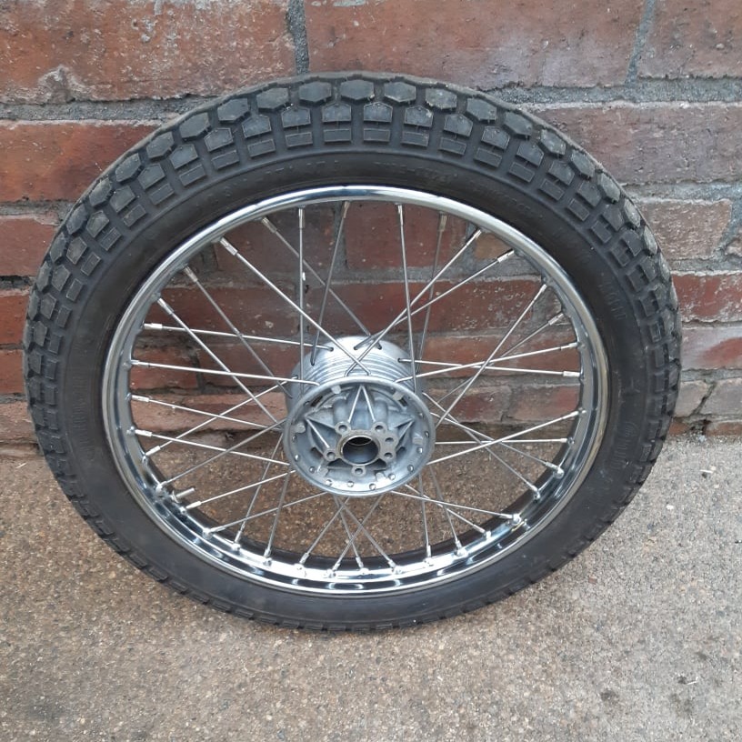
Puch Wheel Rebuild
Some information on rebuilding the Puch wheels, with new spokes, bearings and seals.
Some information on rebuilding the Puch wheels, with new spokes, bearings and seals.
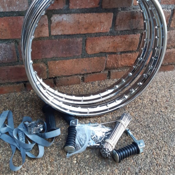
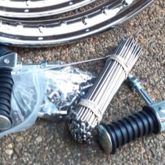
Some replacement parts are shown here. New stainless spokes and chrome rims were ordered and bearings and seals.
Replacement wheel bearings are a standard size:
15mm ID x 32mm OD x 9mm
The seals are:
15mm ID x 32mm OD x 5.5mm
Spoke specification was 168mm long with a 45° bend at the root.
Original diameter was 3mm with a 3.5mm thread but these were not available so 3.2mm spokes were used.
These were a bit tight for the threading pattern a better idea would be 2.8mm or 2.6mm.
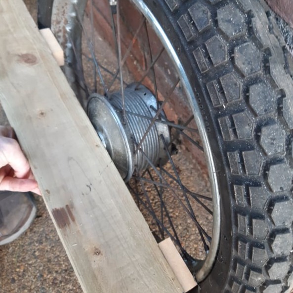
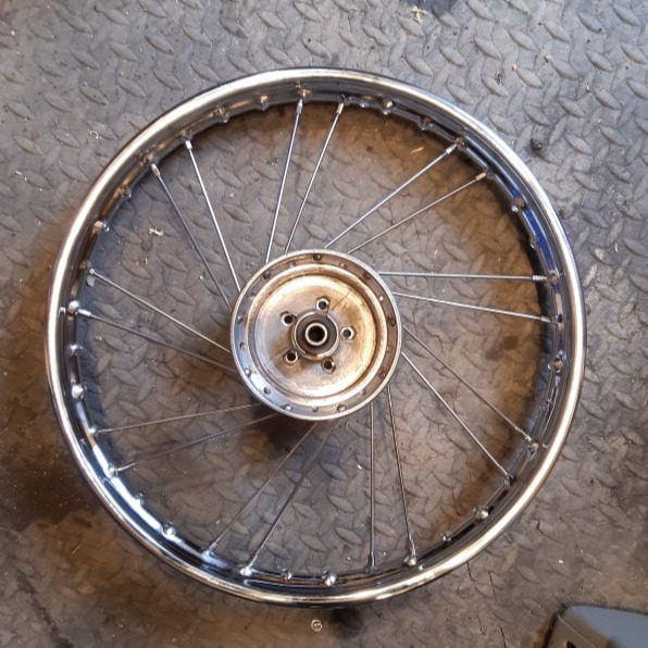
Before dismantling the old wheels, a note needs to be made of the rim off-set. In this case a wooden gauge was made up consisting of a straight edge and some sanded blocks.
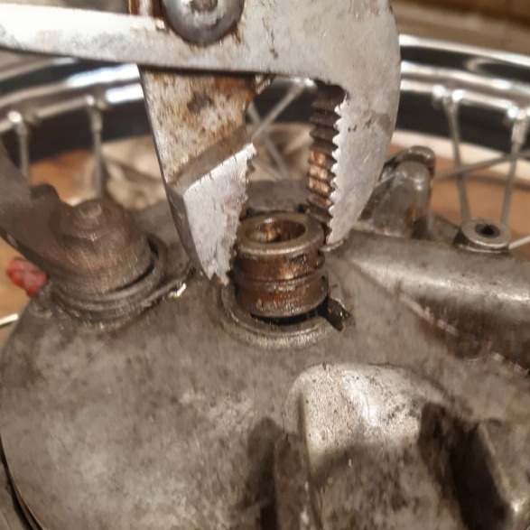
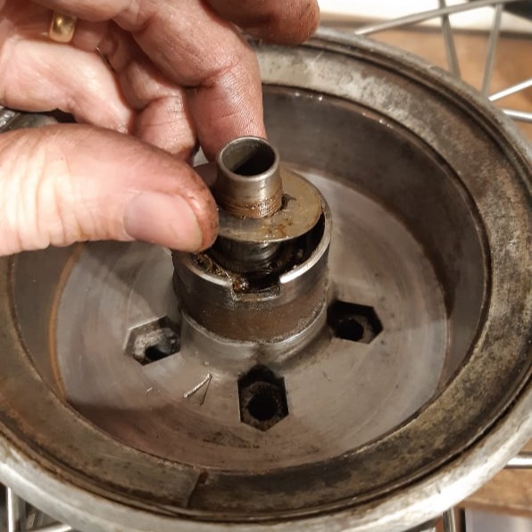
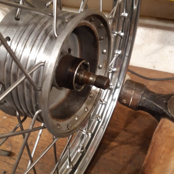
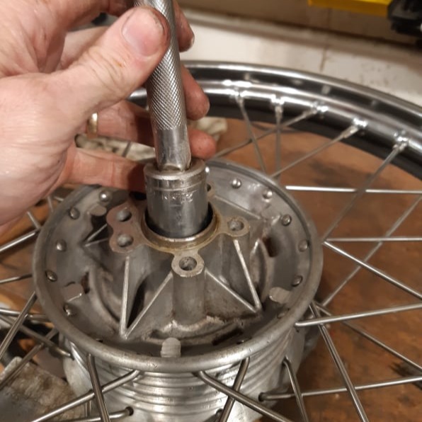
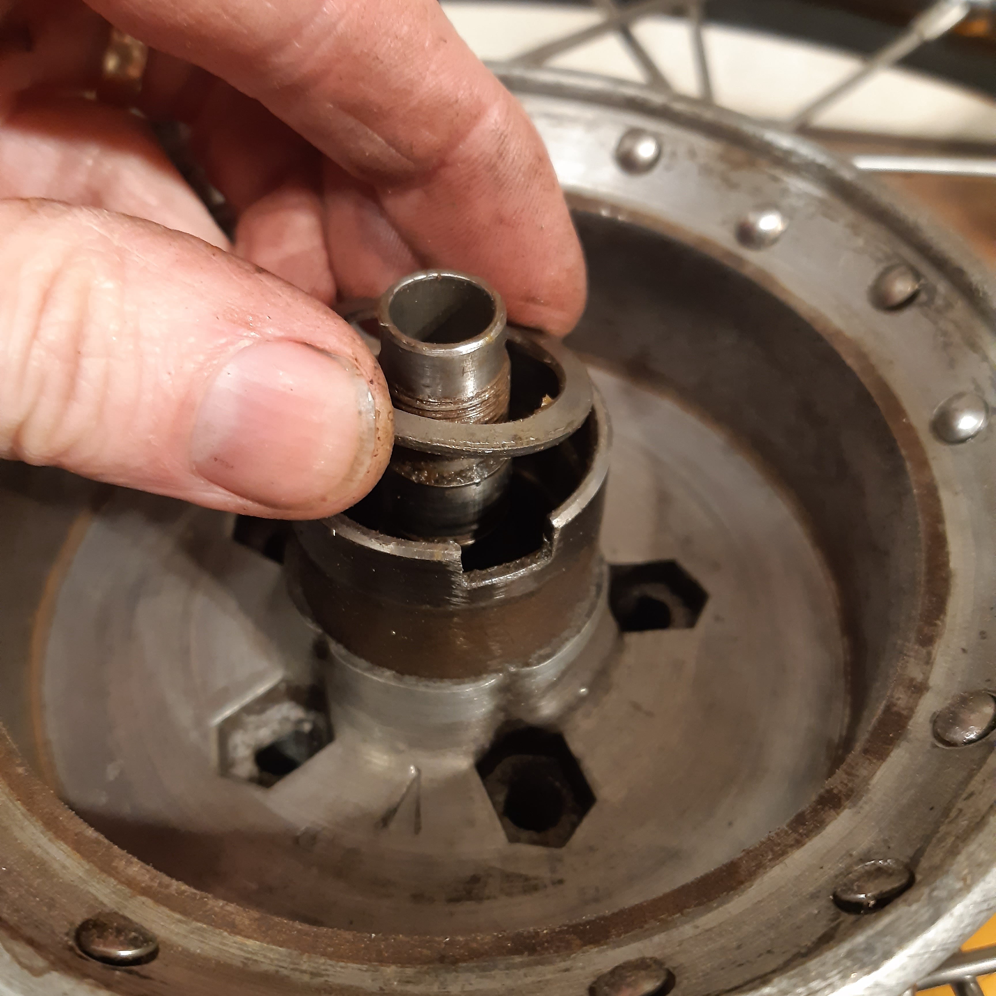
To dismantle the hub, the axle spacer must be removed....
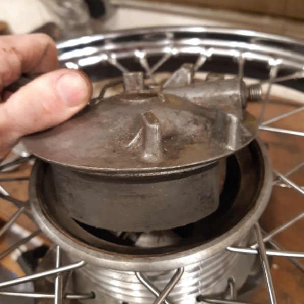
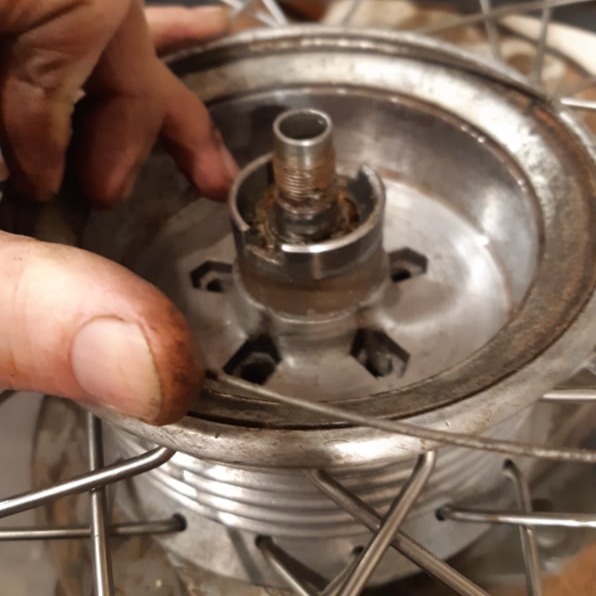
....and then the brake can be extracted.
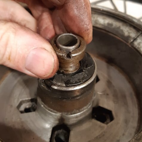
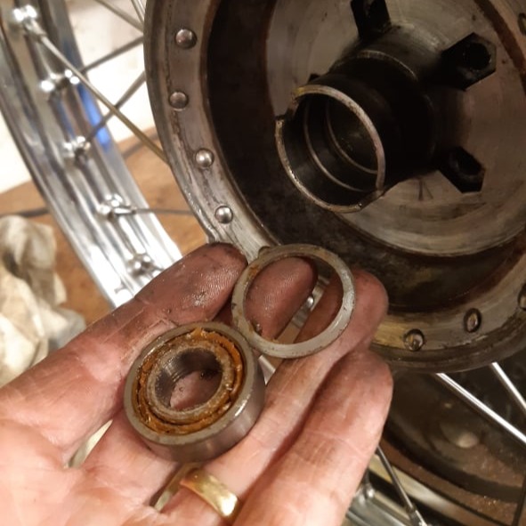
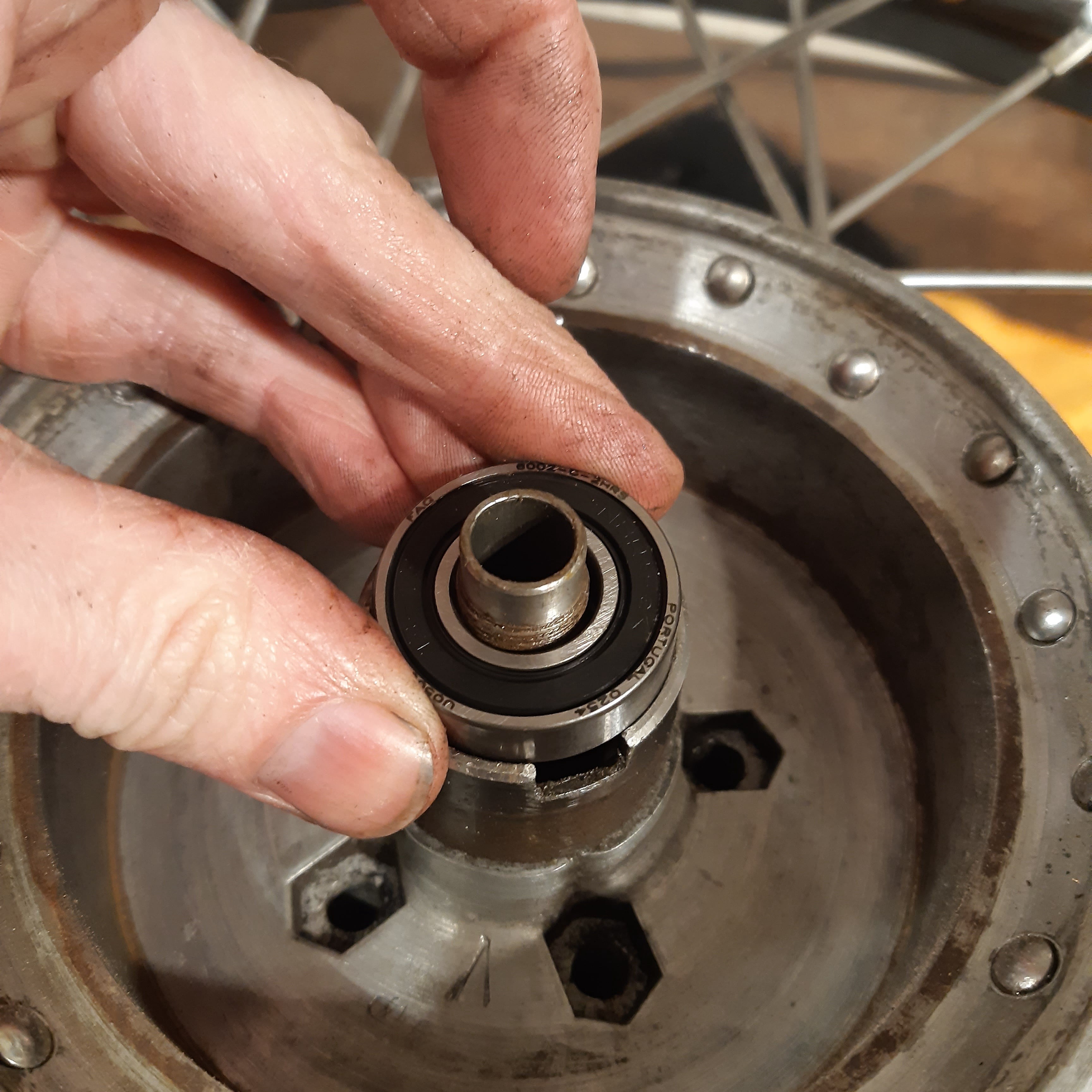
Inside the brake, the screw collar is next to come out.
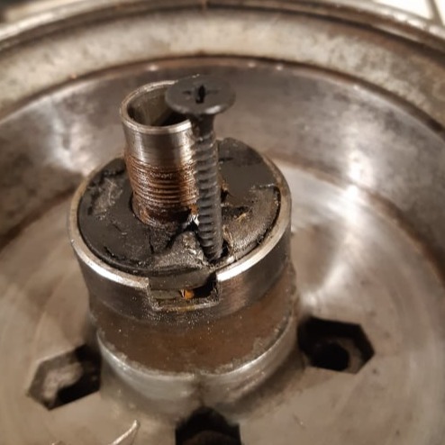
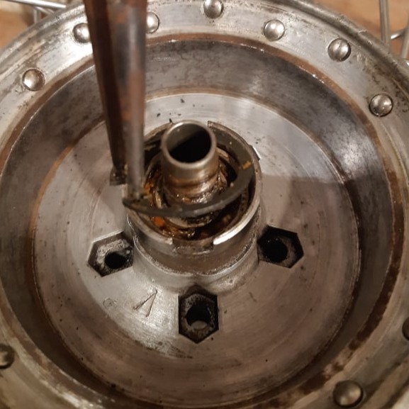
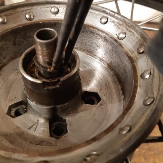
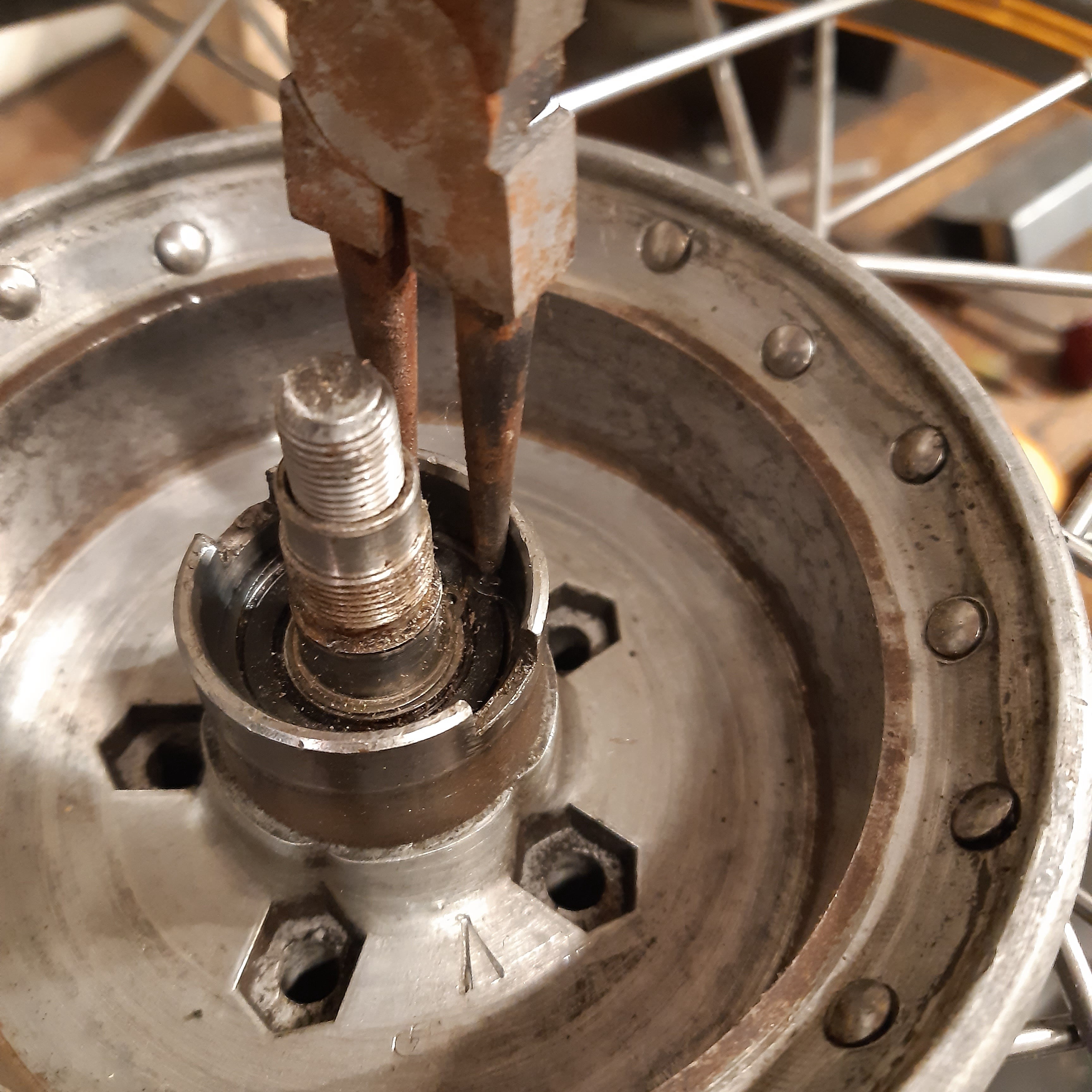
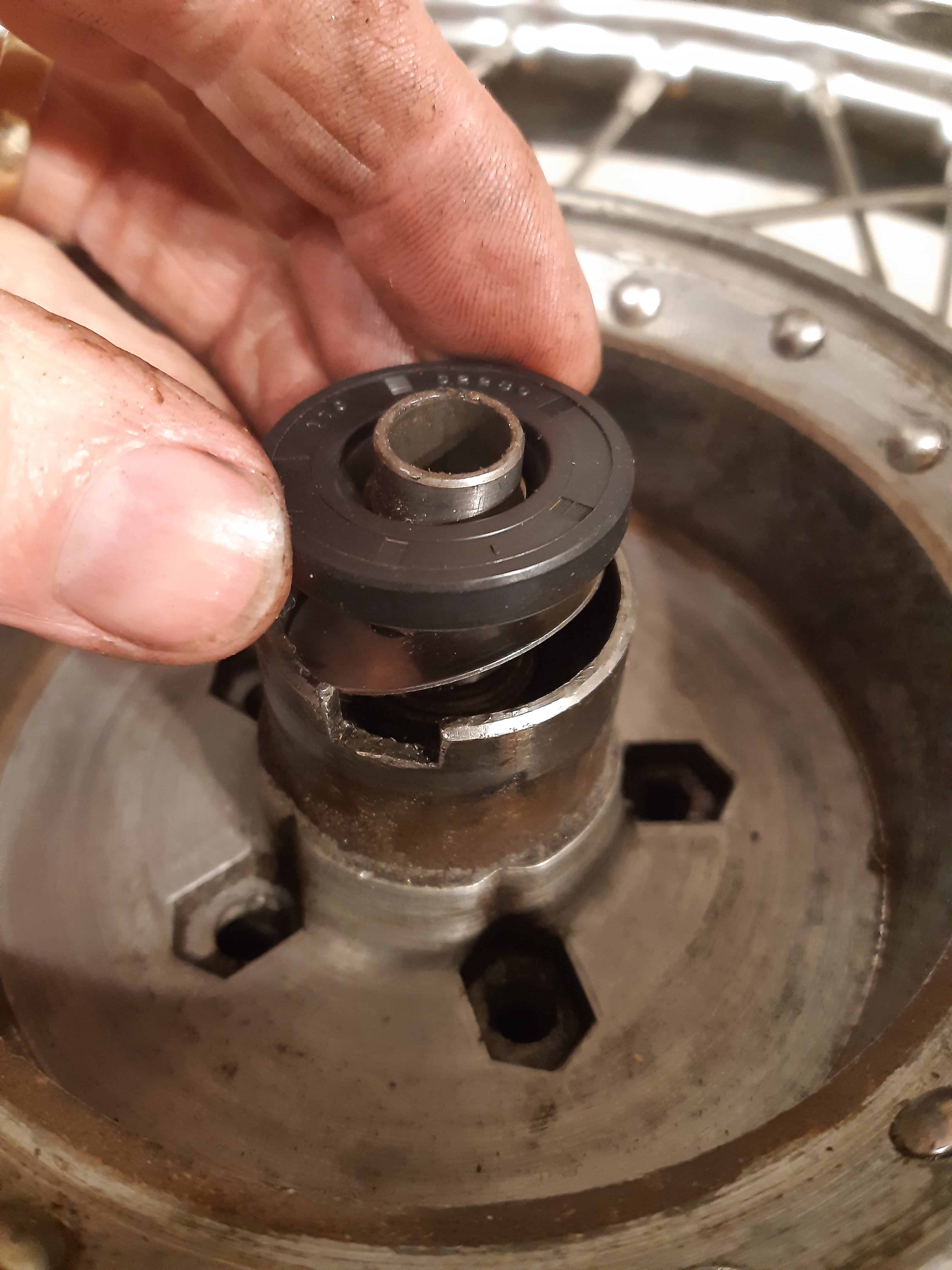
If the bearing seal is stuck, a self tapping screw can be driven into it, and used to lift it out.
Behind the seal the shim washer can be extracted with a magnet and/or a dental pick (and some patience).
To access the spoke heads the wire spring ring must be removed using a small flat blade screwdriver.....

....followed by the spoke cover.
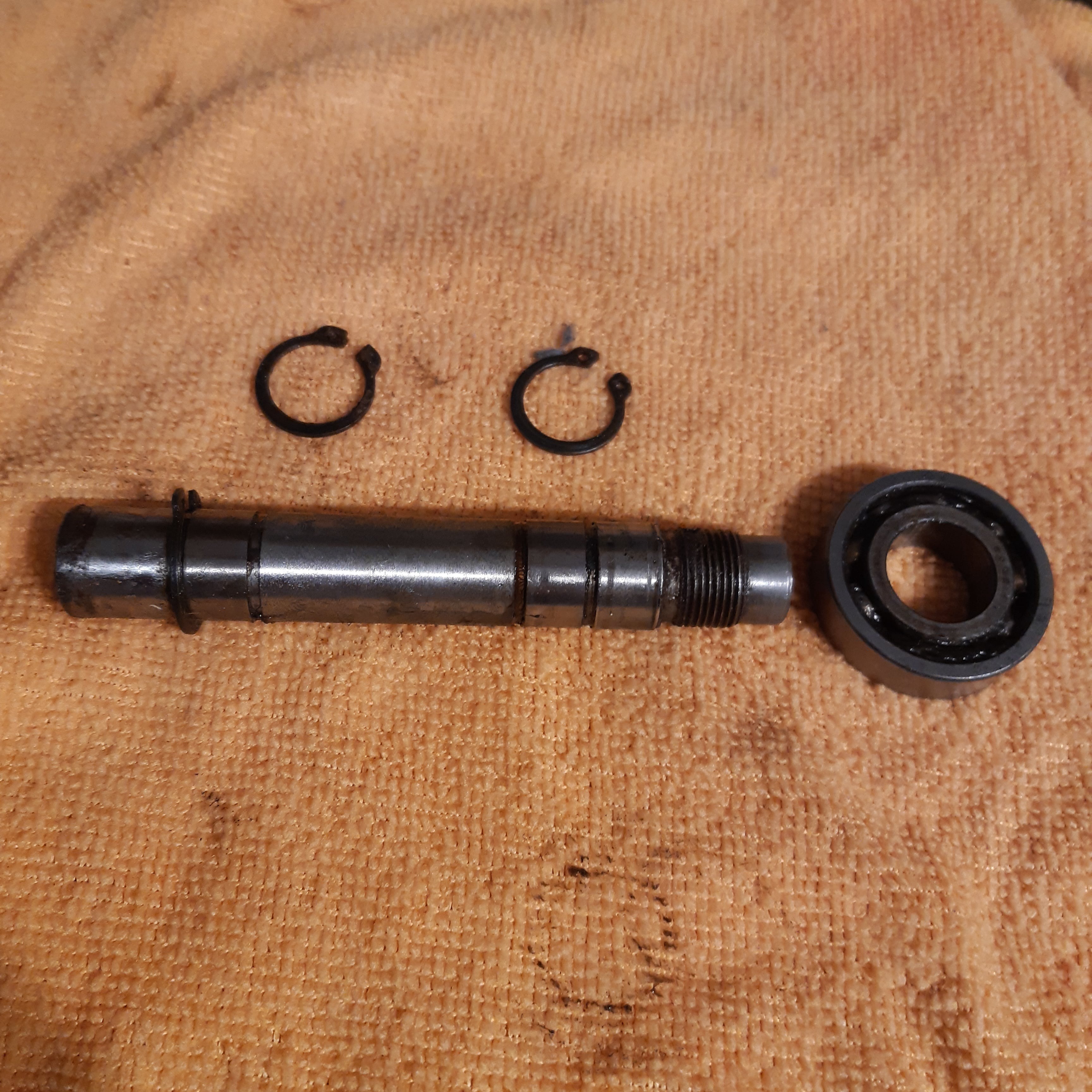
Circlip pliers are needed to remove both the outer.....
....and inner circlips.....
....and then the axle, complete with the left hand bearing, can be drifted from the wheel hub, using the axle spindle as a drift to protect the hollow axle.
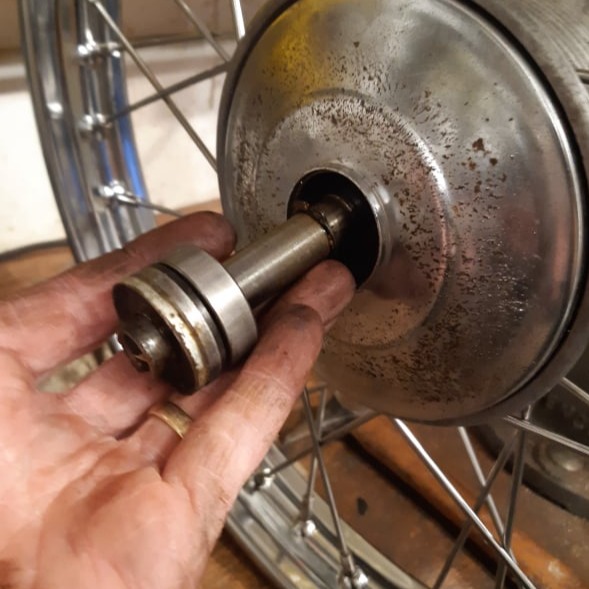
Axle and bearing removed.
The left side hub cover can be removed with a brass or plastic drift.
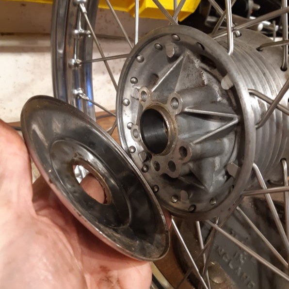
Removing the hub cover.
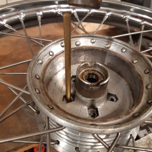
The remaining bearing can be drifted from the hub using a suitable socket and hammer.
Be sure to retain any thrust washers in the system.
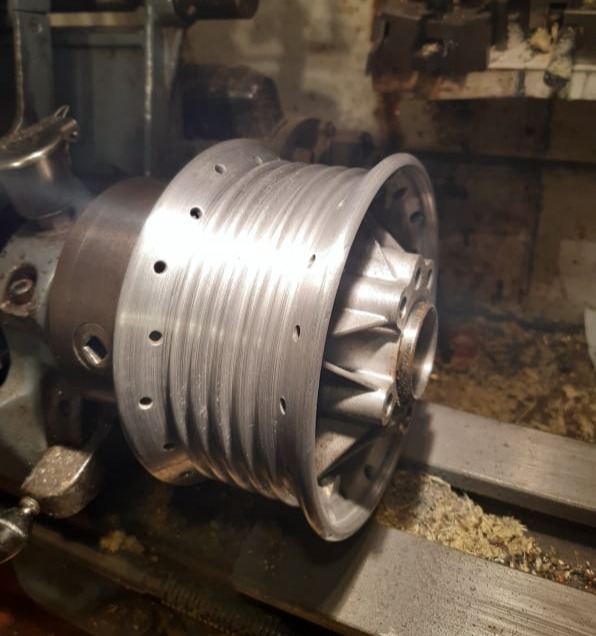
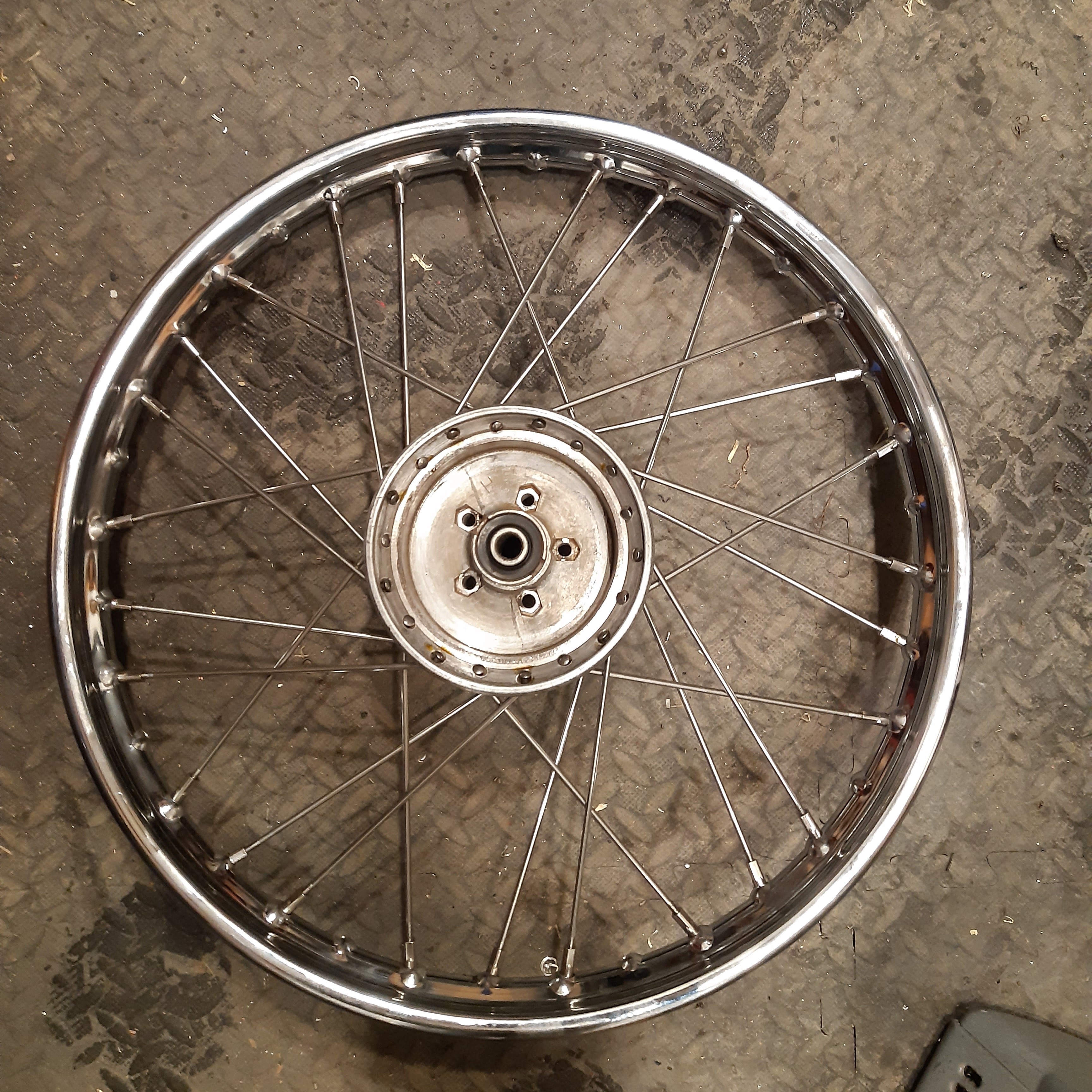
Once the spokes have been removed, the hub can be checked and cleaned.
The remaining bearing can be drifted from the axle.
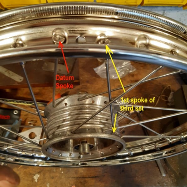
To re-lace the wheel the valve hole on the rim can be used as a datum.
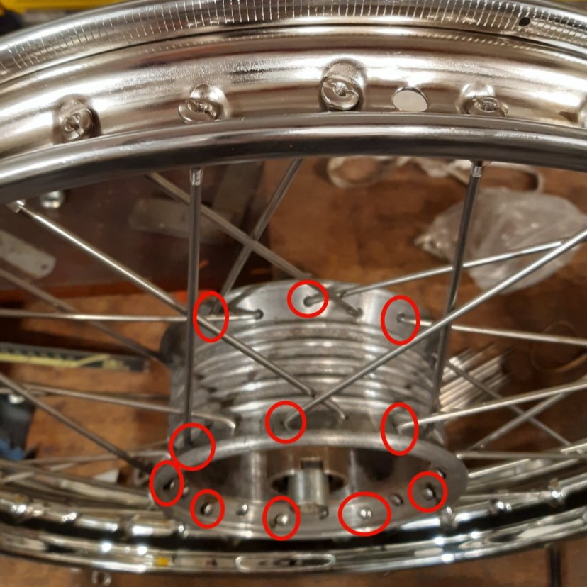
Note that, because the spokes are all threaded from one side of the hub (unlike a bicycle hub) the spokes in the holes highest on the rim were threaded first.
That is to say, the spokes circled in red had to be threaded into the hub first.
The original threading pattern was a cross two spoke pattern which means each spoke should cross 2 others on its way from the hub to the rim.
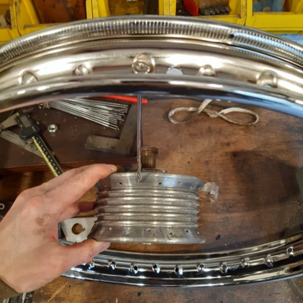
The first spoke (datum spoke) should be threaded to left of the valve hole.
Note the holes on the rim are staggered and should help the spokes point the correct side of the hub.
Working round the hub every-other hole on the hub flange should be connected to every 4th hole on the rim.
Then the hub can be twisted within the rim to ensure the first spoke is pointing away from the valve hole.
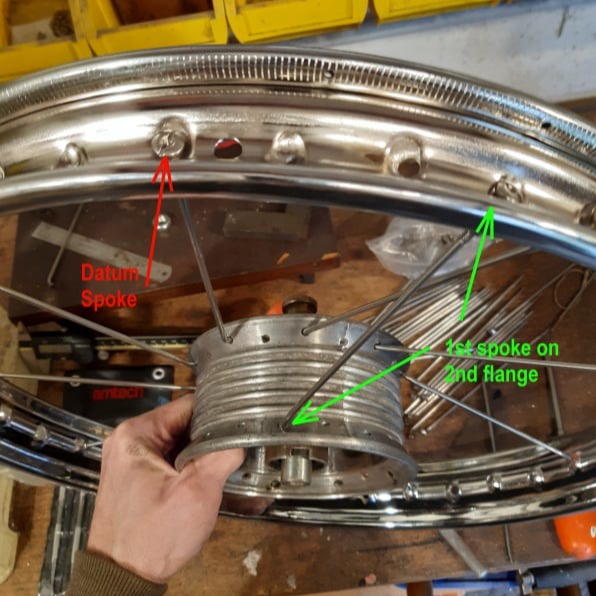
The first spoke on the second flange should be located in the holes shown, relative to the datum spoke.
Following the same pattern as before the second set of spokes should look like this.
The third set of spokes will cross over the first set.
To get started, the first spoke on the first flange is located to the right of the valve hole and located on the hub as shown.
Third set of 9 spokes in place.
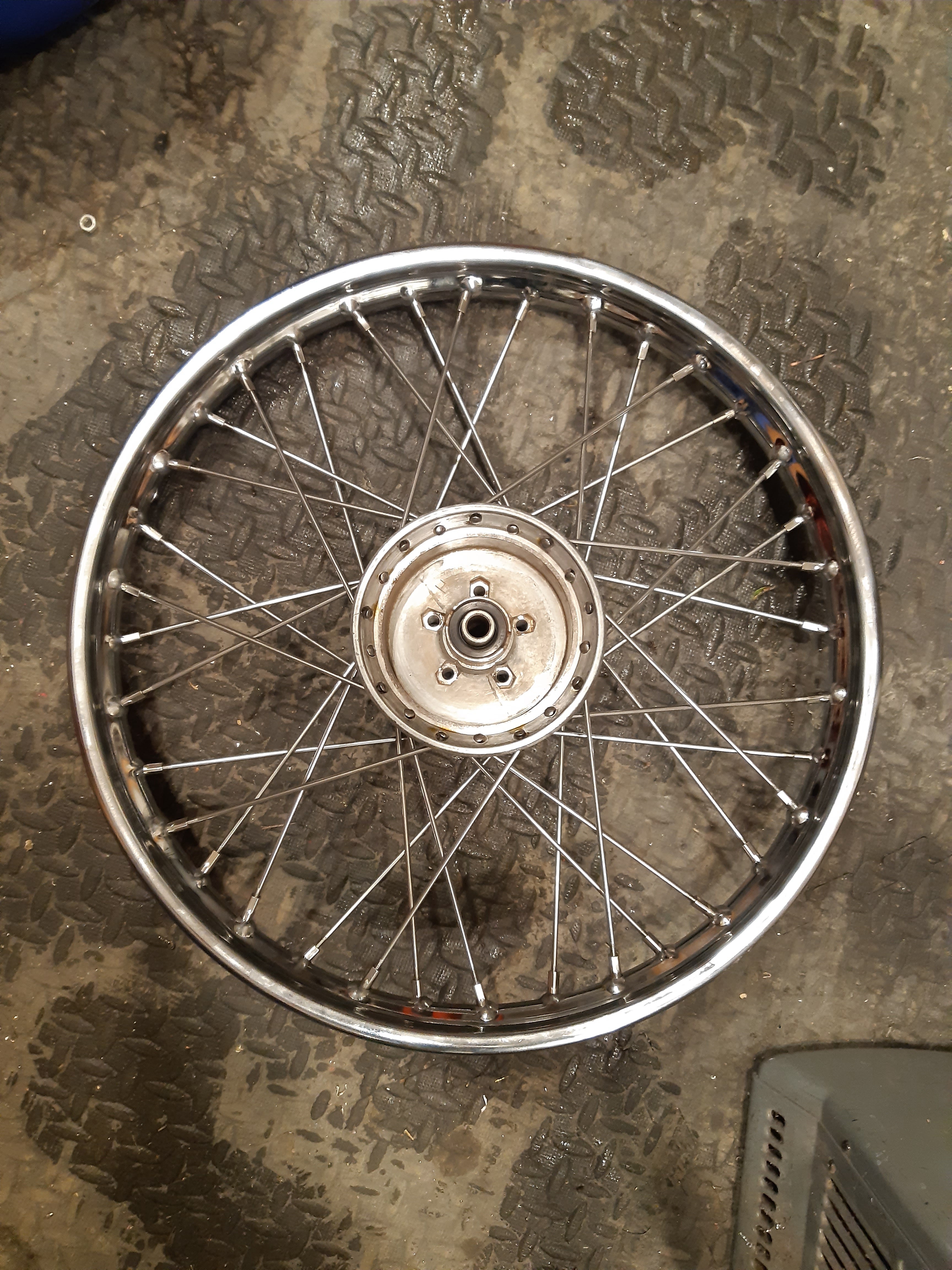
The final 9 spokes should be put in the remaining holes.
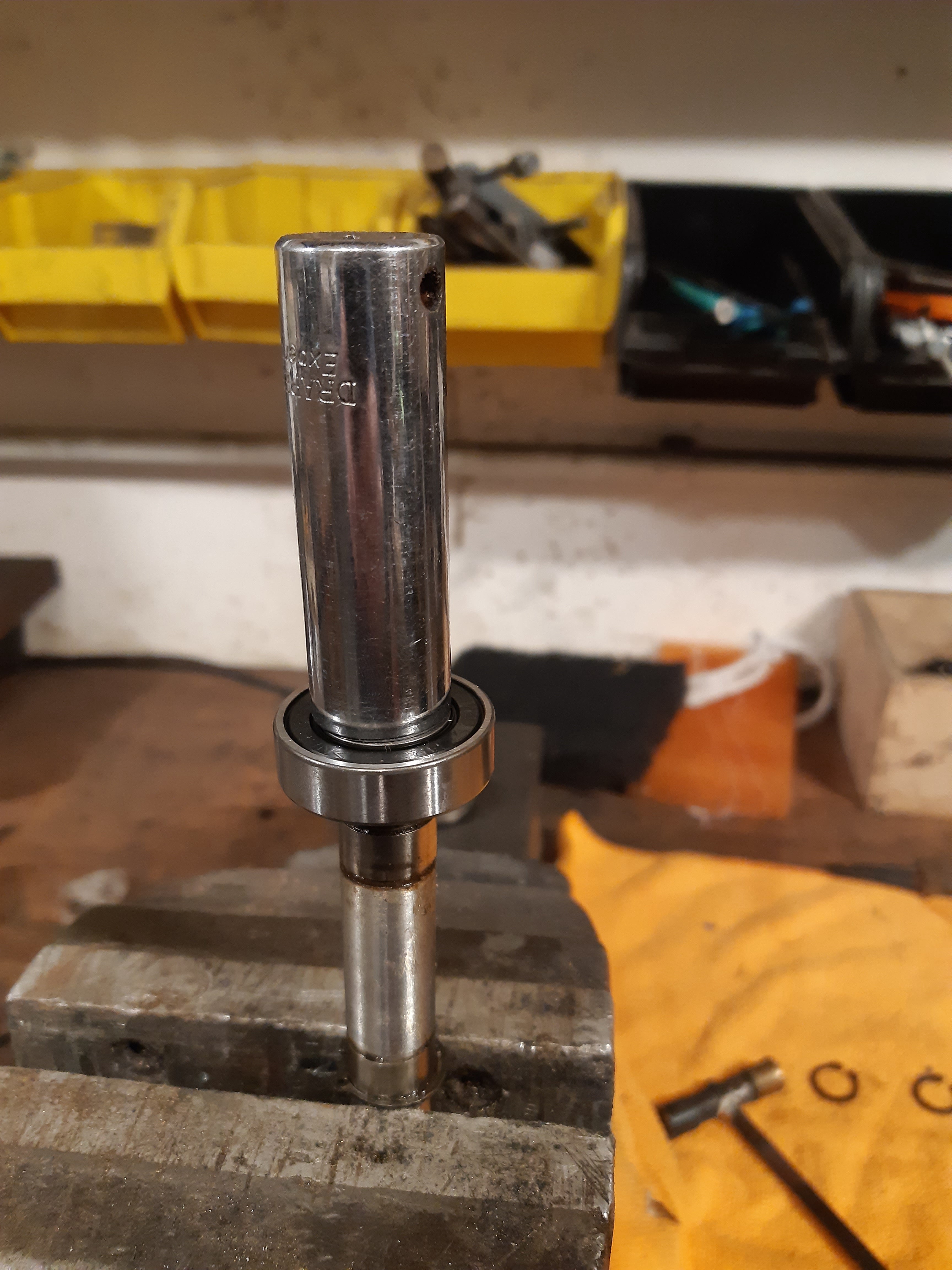
The first bearing is pushed onto the hollow axle using a socket as a drift. It should be pushed down from the threaded end to the only remaining circlip.
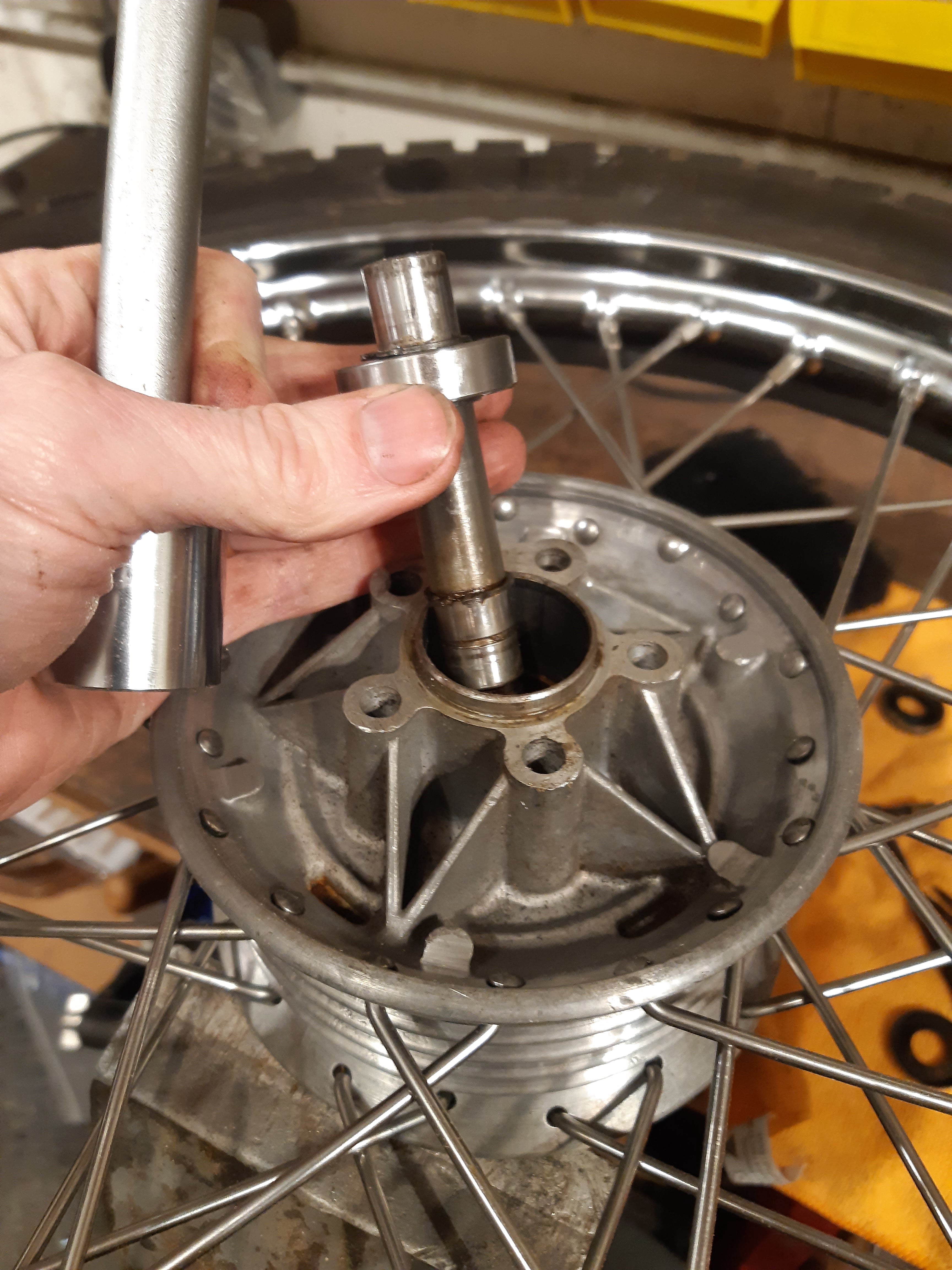
The axle should be inserted from the "cover" side of the wheel....
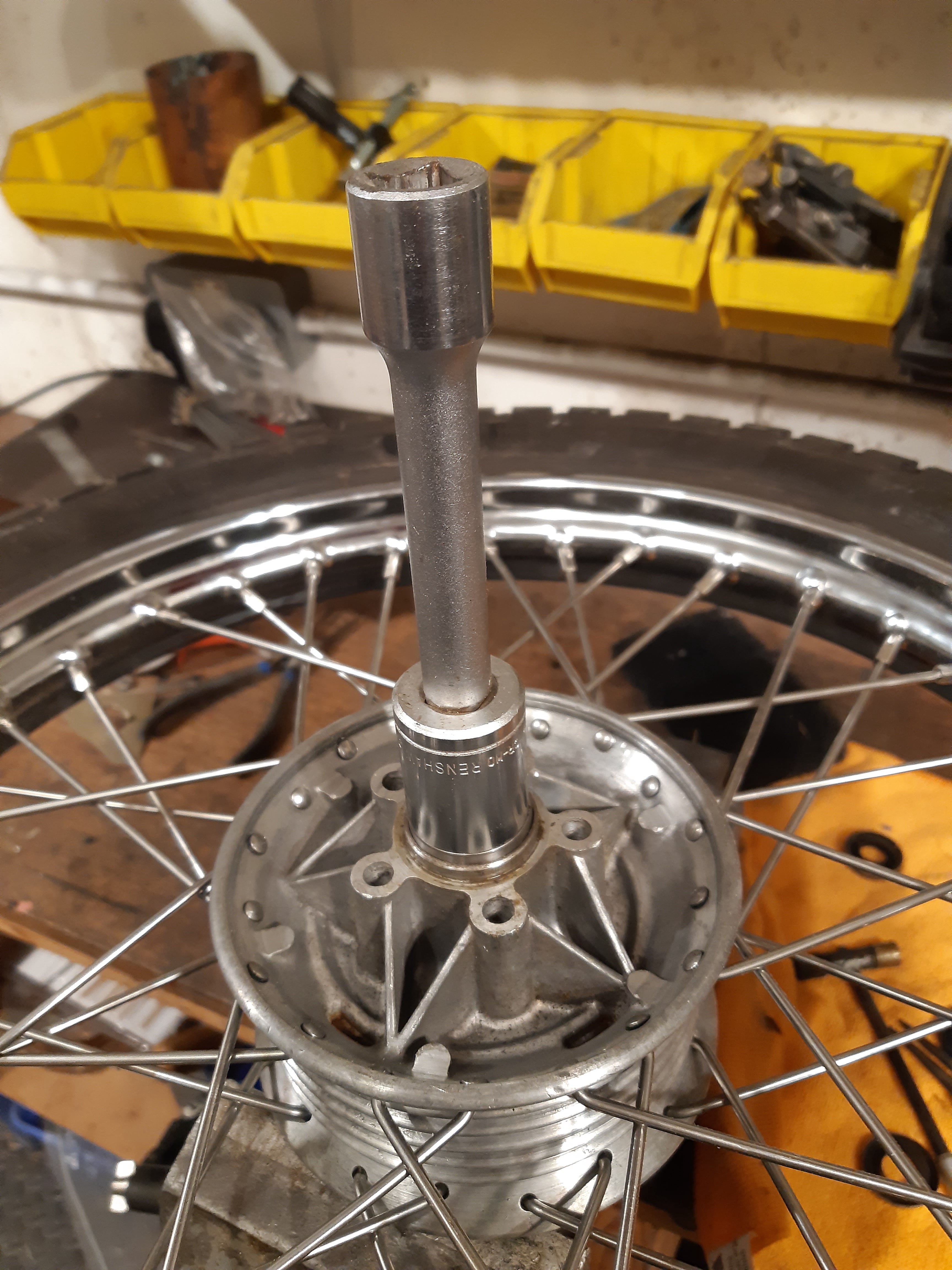
....driven into place using a suitable socket......
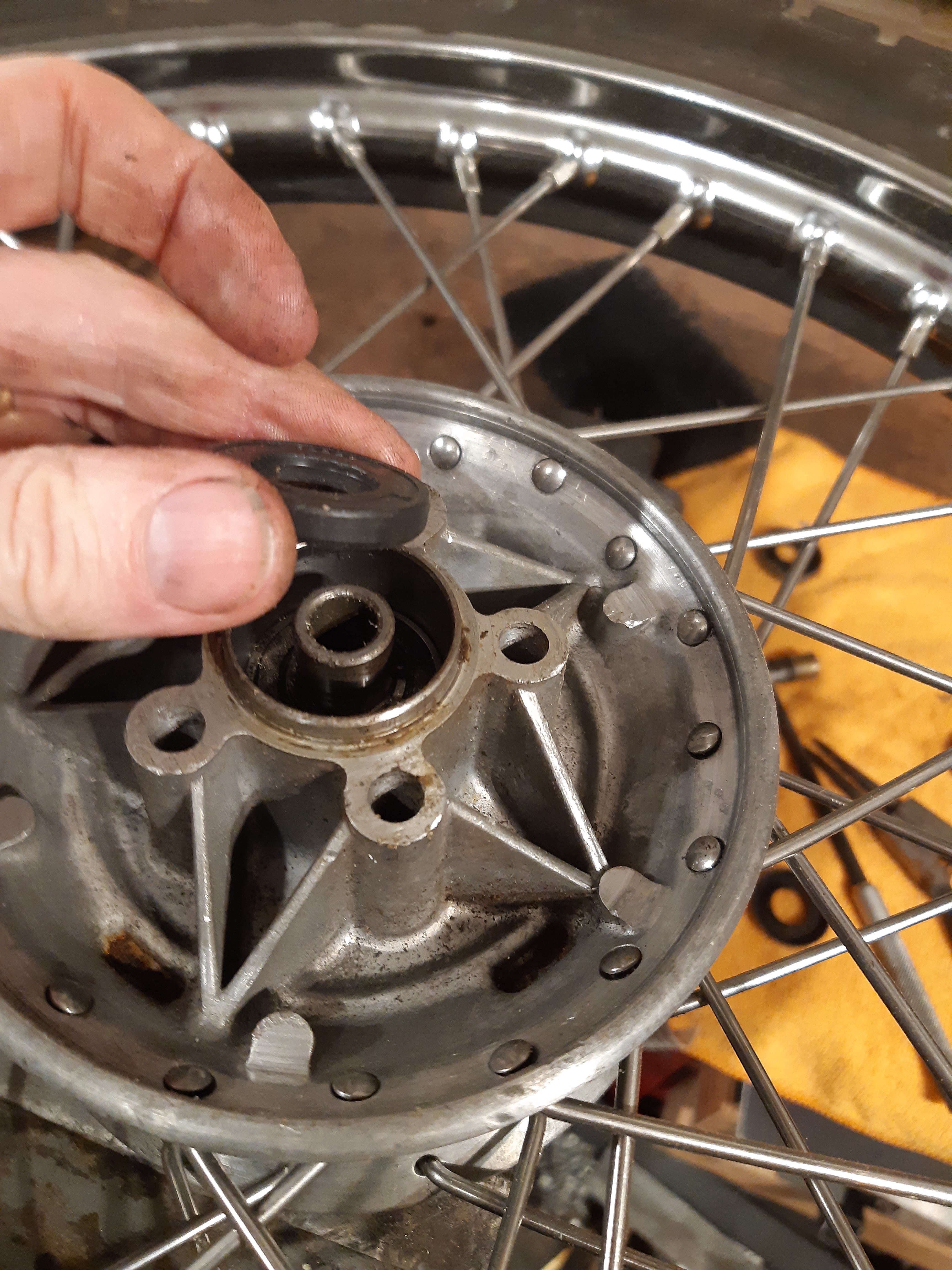
....and followed by the seal.
With the wheel flipped over; the inner circlip should be put on the axle, followed by the inner shim......
.....the second bearing.....
.....two more circlips.....
....and the outer shim and seal.
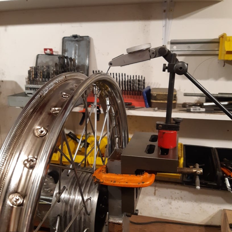
The wheel finish wheel was supported on a length of 10mm threaded rod, in a post clamped in the vice.
An angle plate was clamped to the post to hold a DTI to measure run out.
Progressive adjustments need to be made to get the wheel running true axially and radially.
The dishing gauge can be used to check rim offset.
Finally the torque on each spoke should be checked for the same "note" all round when tapped with the spanner.

HTML Maker