Puch VF/VZ50 Engine Overhaul
This page to provide some help to a basic strip-down and rebuild of the Puch VZ50 engine and gearbox.
This page to provide some help to a basic strip-down and rebuild of the Puch VZ50 engine and gearbox.
To remove the engine from the bike, the exhaust, and carburetor need to be removed, followed by both pedals so the chain can be disconnected.
The three engine bolts were then undone and the engine supported whilst the bolts were withdrawn from the chassis.
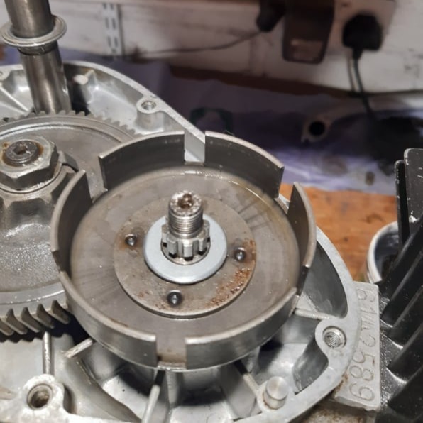
With the engine on the bench the side cover can be removed to reveal the clutch mechanism.
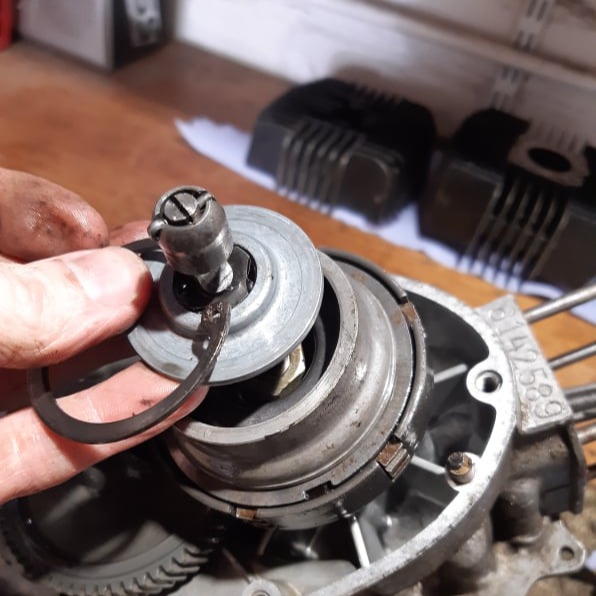
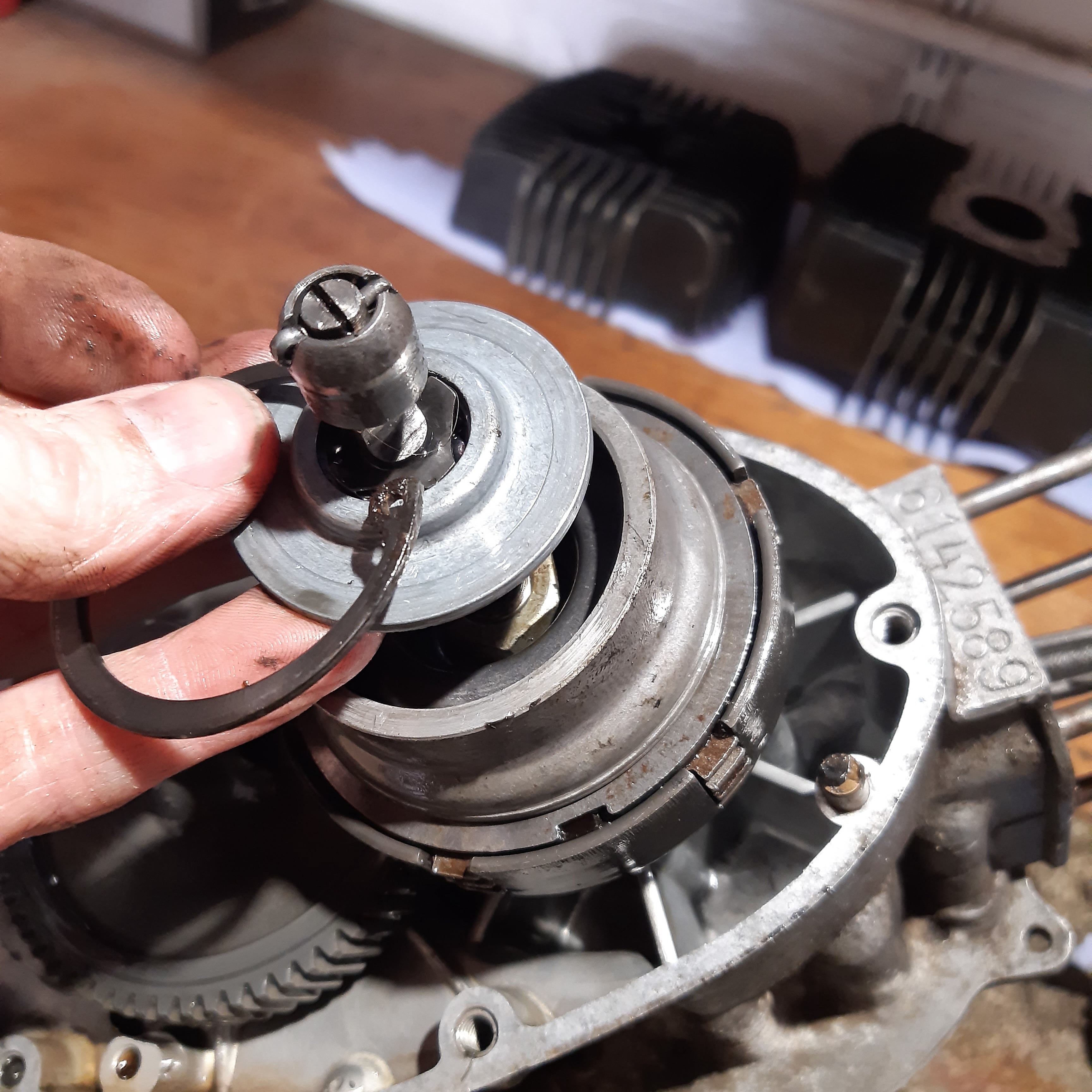
The clutch thrust bearing is removed by first unclipping the circlip, to reveal the clutch bolt.
On the other side of the case, the housing over the flywheel can be removed.
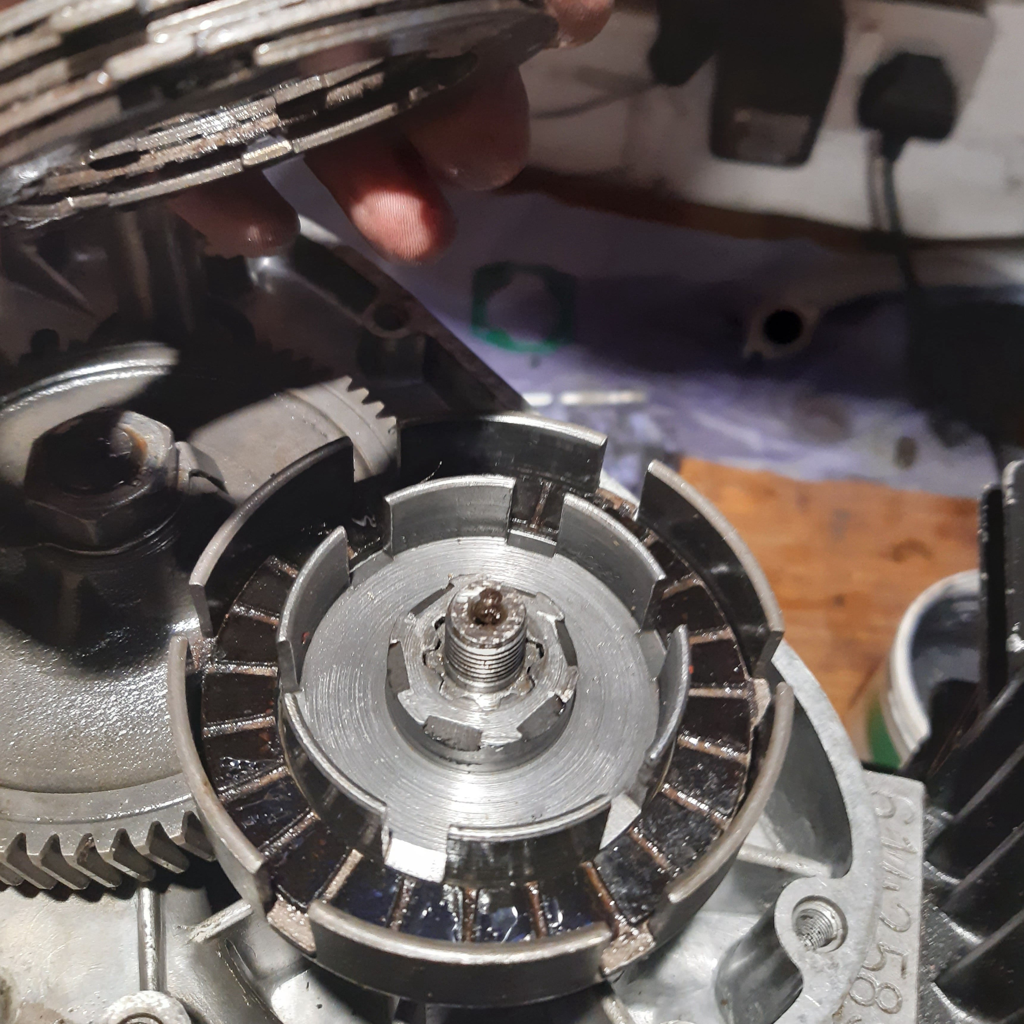
To undo the flywheel centre bolt, clutch centre bolt, primary gear bolt and extract the flywheel, the piston need to be held. This can be done by passing some thick rope through the spark plug hole, providing a secure but soft way to stop the engine turning.
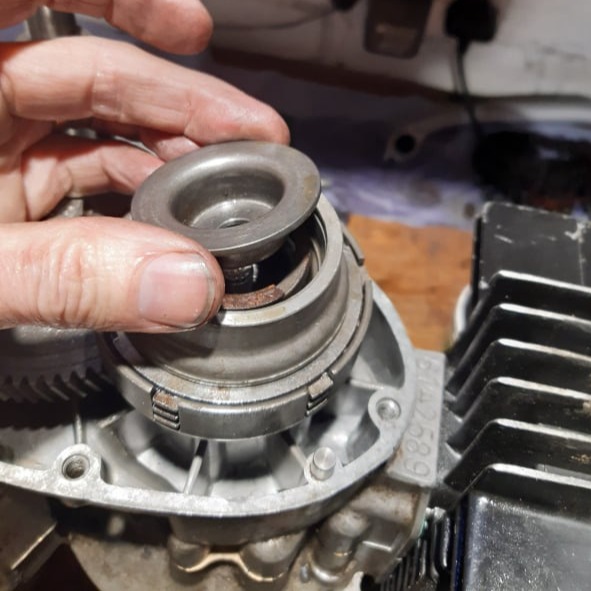
Removing clutch top can be removed........
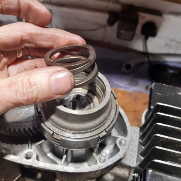
....followed by the clutch spring......
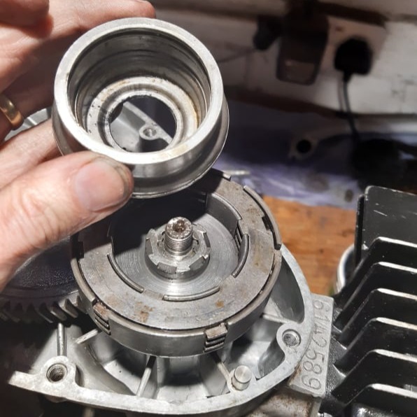
....spring cage....
....clutch plates.....
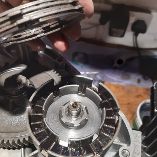
...and clutch basket.
Under the clutch assembly there is a thrust washer and circlip to remove.
Finally on this side of the engine, the washer and circlip from the pedal shaft should be removed, followed by the primary gear.
On the flywheel side of the engine an extractor tool was used to pull the flywheel off the crank.
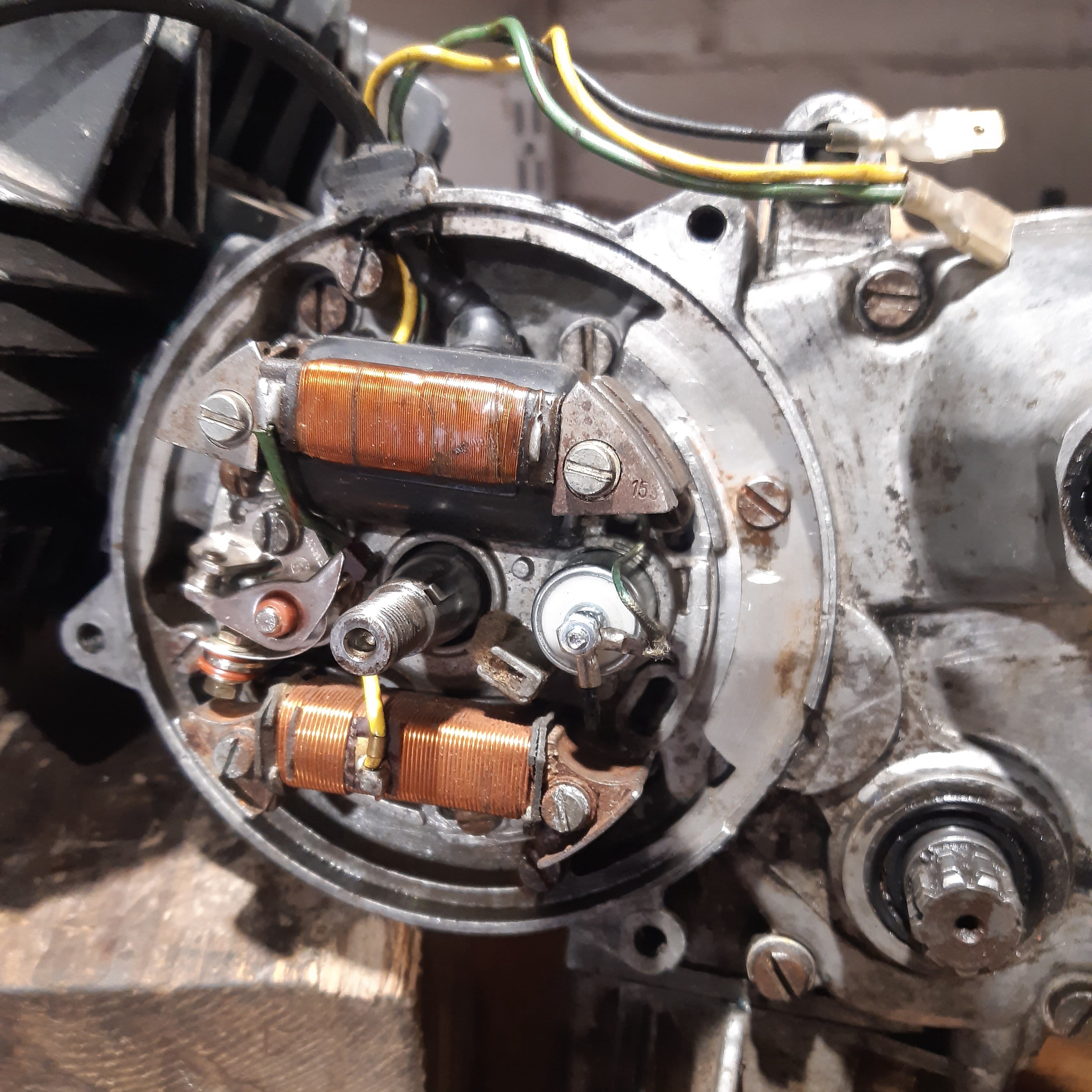
Behind the flywheel the stator plate position was marked to try and retain the engine timing and then the three screws were removed to lift the stator plate clear,
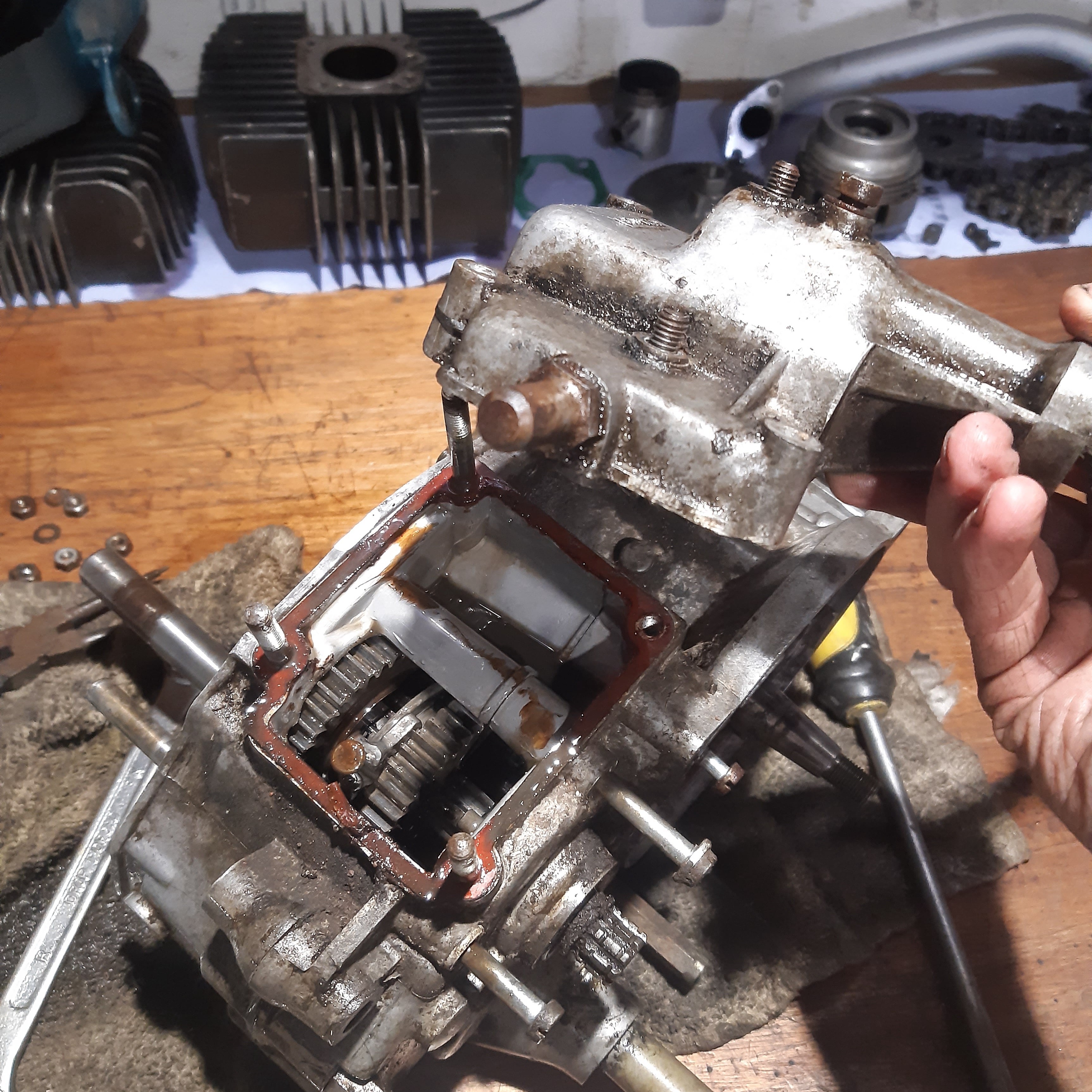
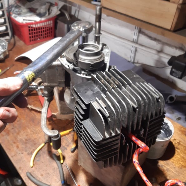
Before splitting the crankcase, the foot change mechanism and cylinder need to be removed.
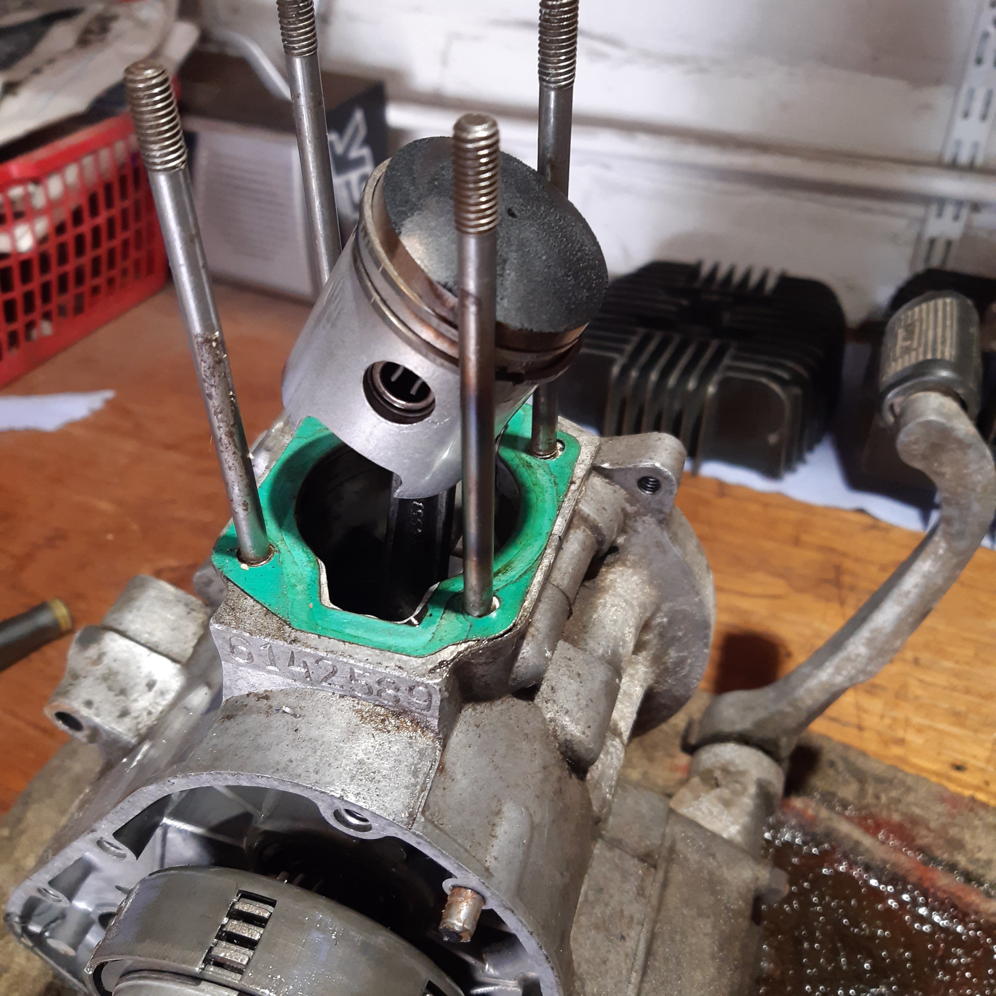
Cylinder removed.
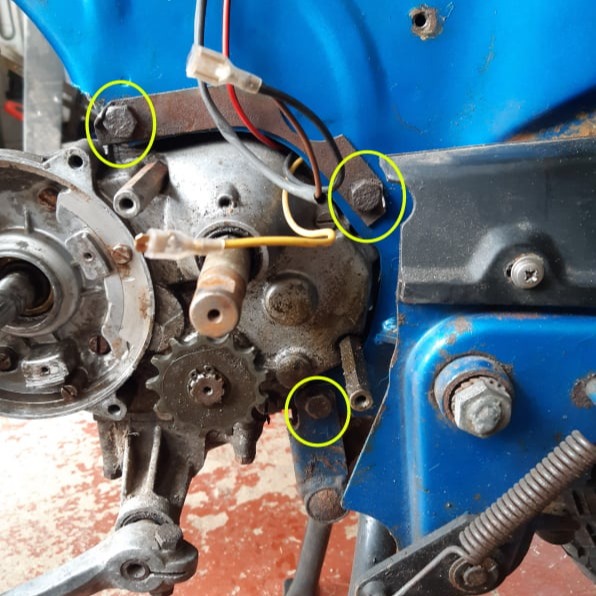
To split the crankcase, the seven crankcase screws and two stand-off bolts (for the chain guard) must be undone.
Then the crank can then be eased apart.
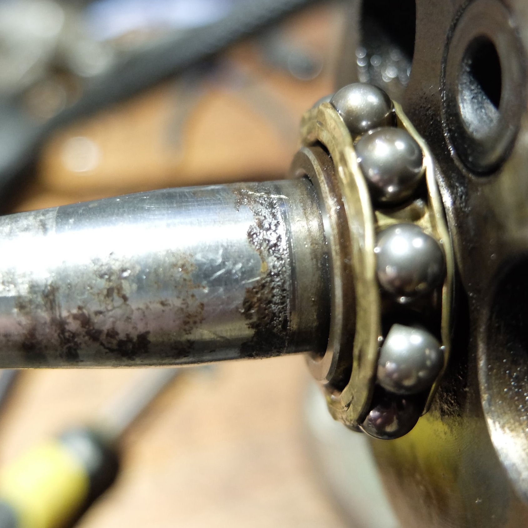
The crank can be removed and inspected. This example had some pitting where the crank seal ran on the shaft.
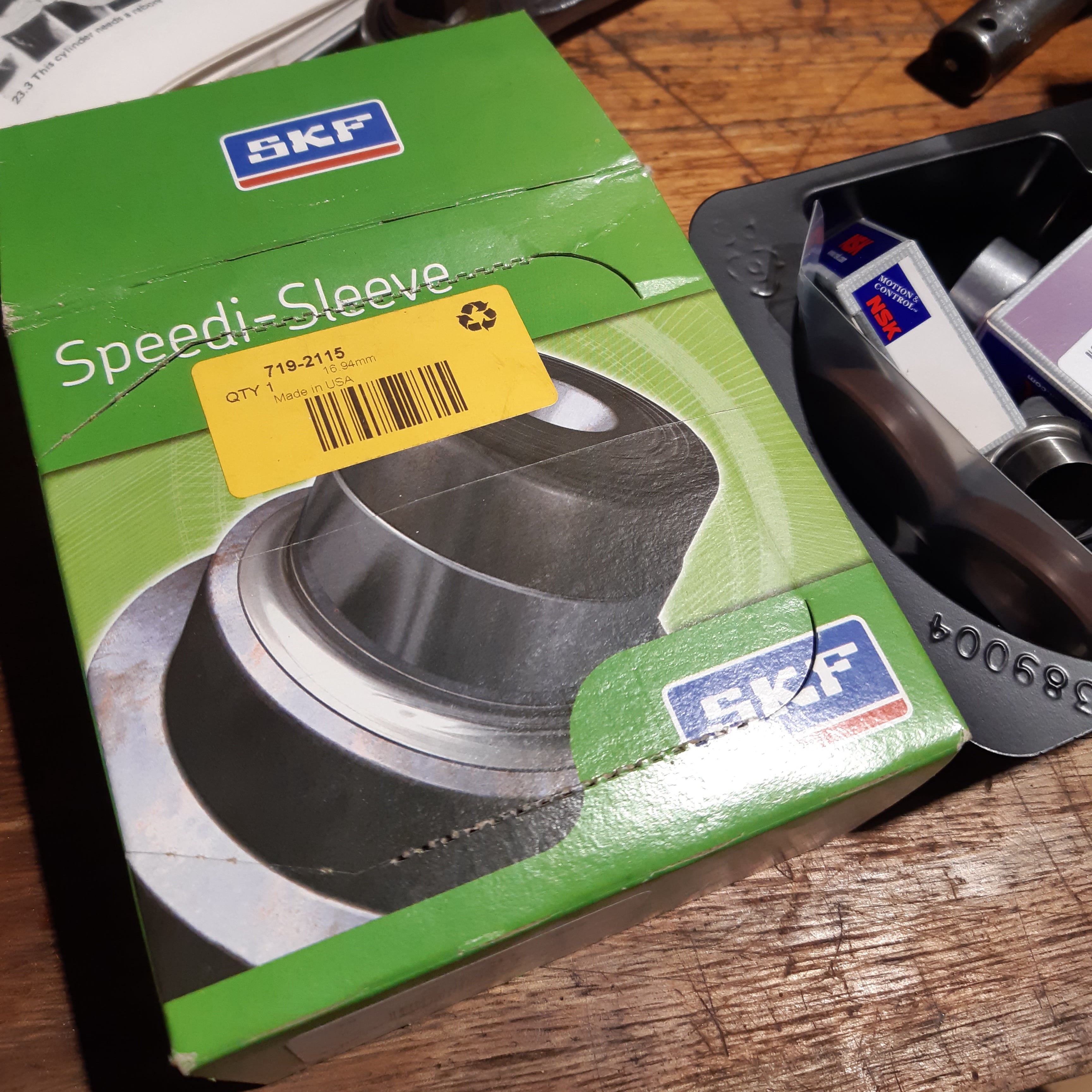
This was repaired with a speedi-sleeve kit for a 17mm shaft.
Speedi-sleeve fitted.
The crank assembly should be inspected for wear. The big end bearings should have no radial play at all, although some side-to-side movement is acceptable. Replacement of this bearing is a job for a two stroke specialist to press the crank apart and re-align it on assembly.
Any play on the little end bearing requires the bearing and gudgeon pin to be replaced, as they are manufactured in matched pairs.
In 2-strokes it is always worth replacing the crank seals. Crank seal orientation is different on the left and right sides of the engine.
In both cases the open side of the seal should face the clutch.
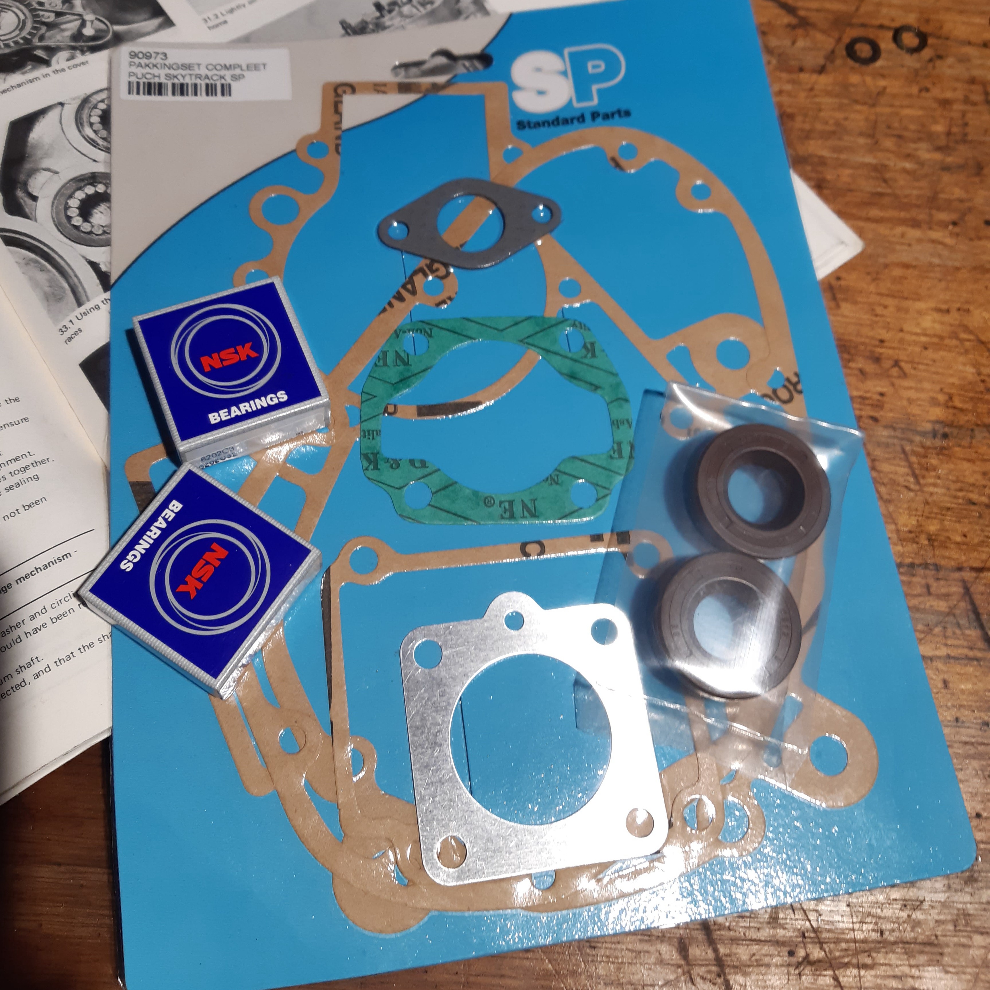
For the reassembly, new gaskets will be needed along with new bearings and seals.
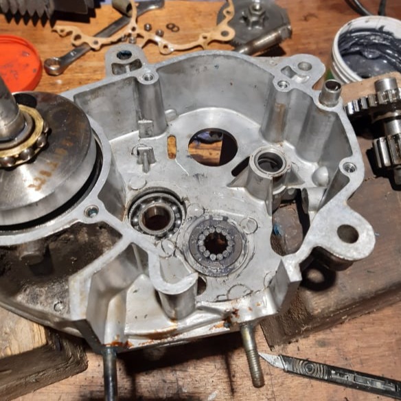
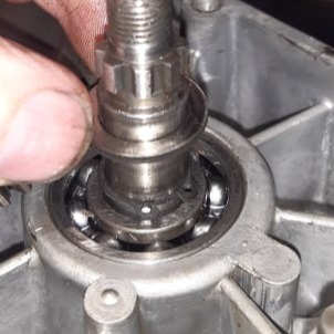
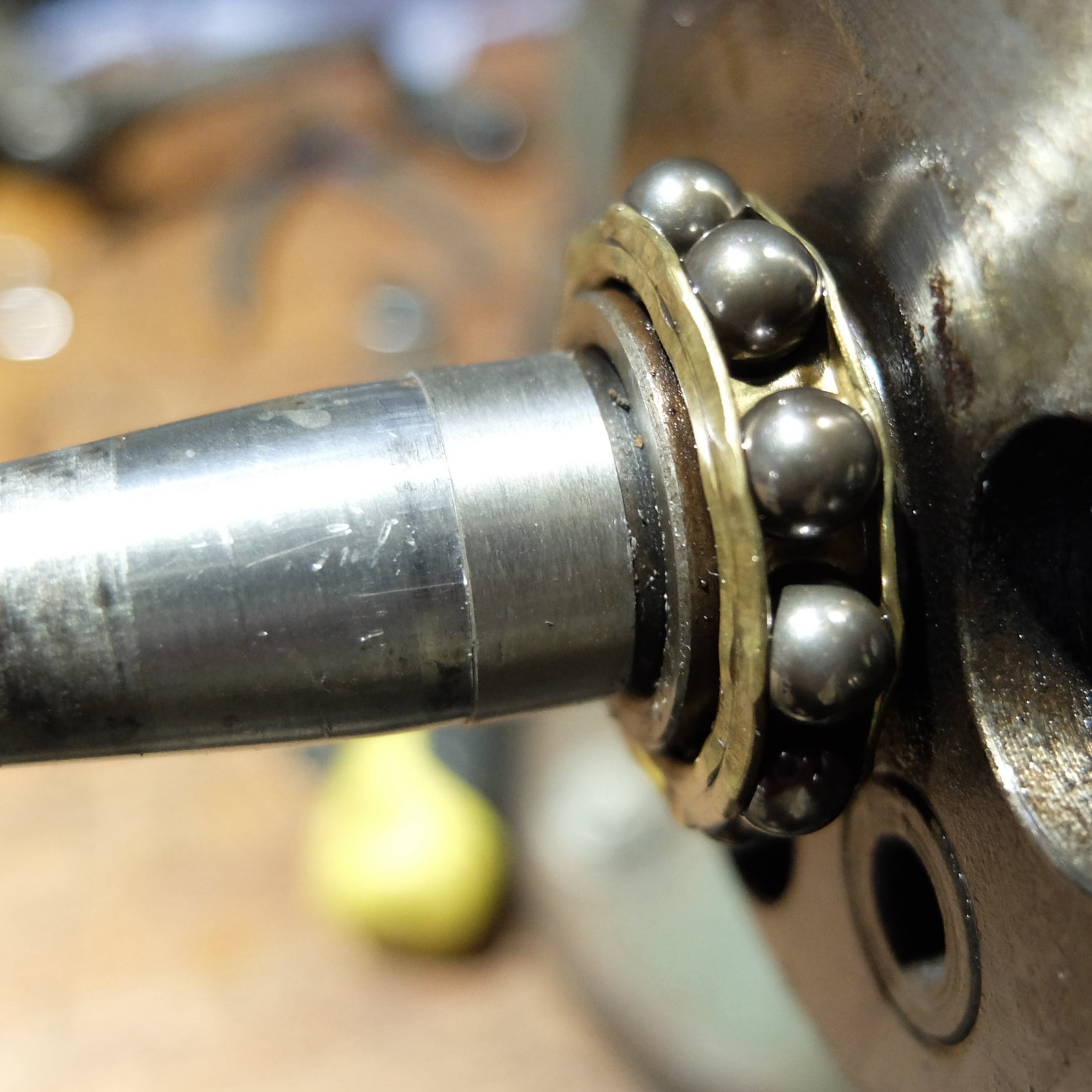
Reassembly starts with the right side engine case. The 14 loose roller bearings are best held in with grease.
The crank can be Inserted too.
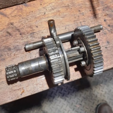
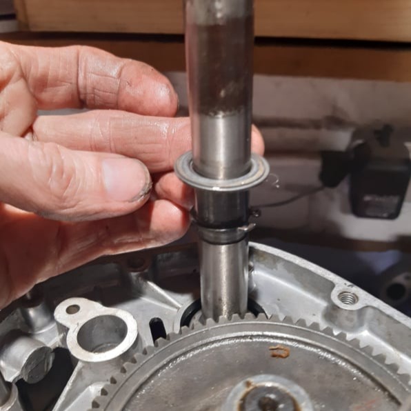
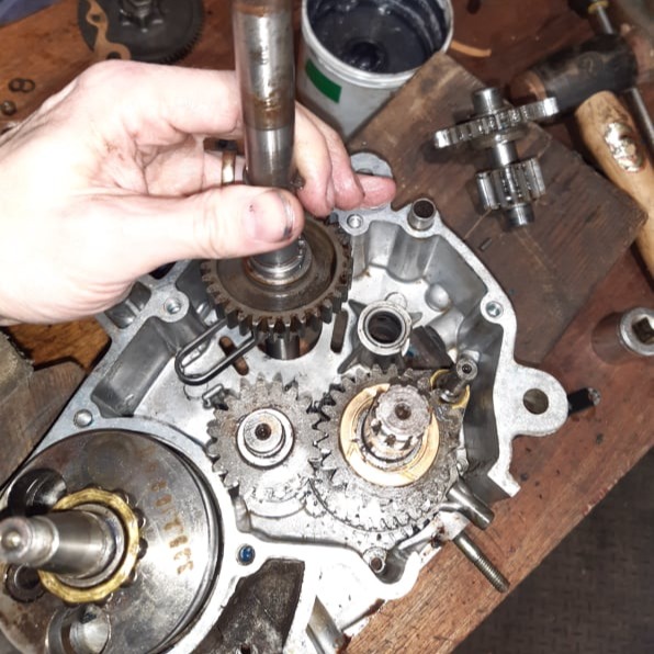
The output shaft can be preassembled and should be placed into the loose needle roller bearing......
...followed by the 3rd gear...
... and the bronze bearing washer.
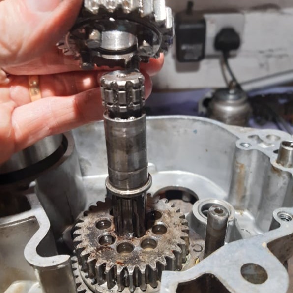
The input shaft assembly has to be inserted with the 2nd gear collars where shown.
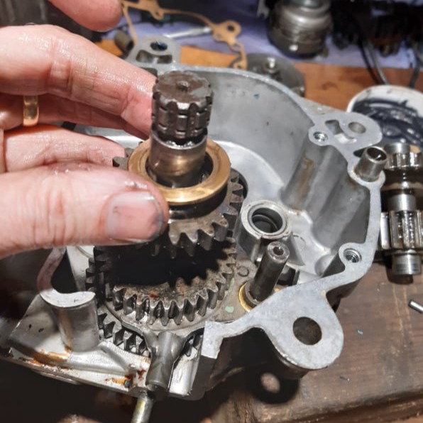
The pedal shaft is next with the friction spring correctly located in the housing features.
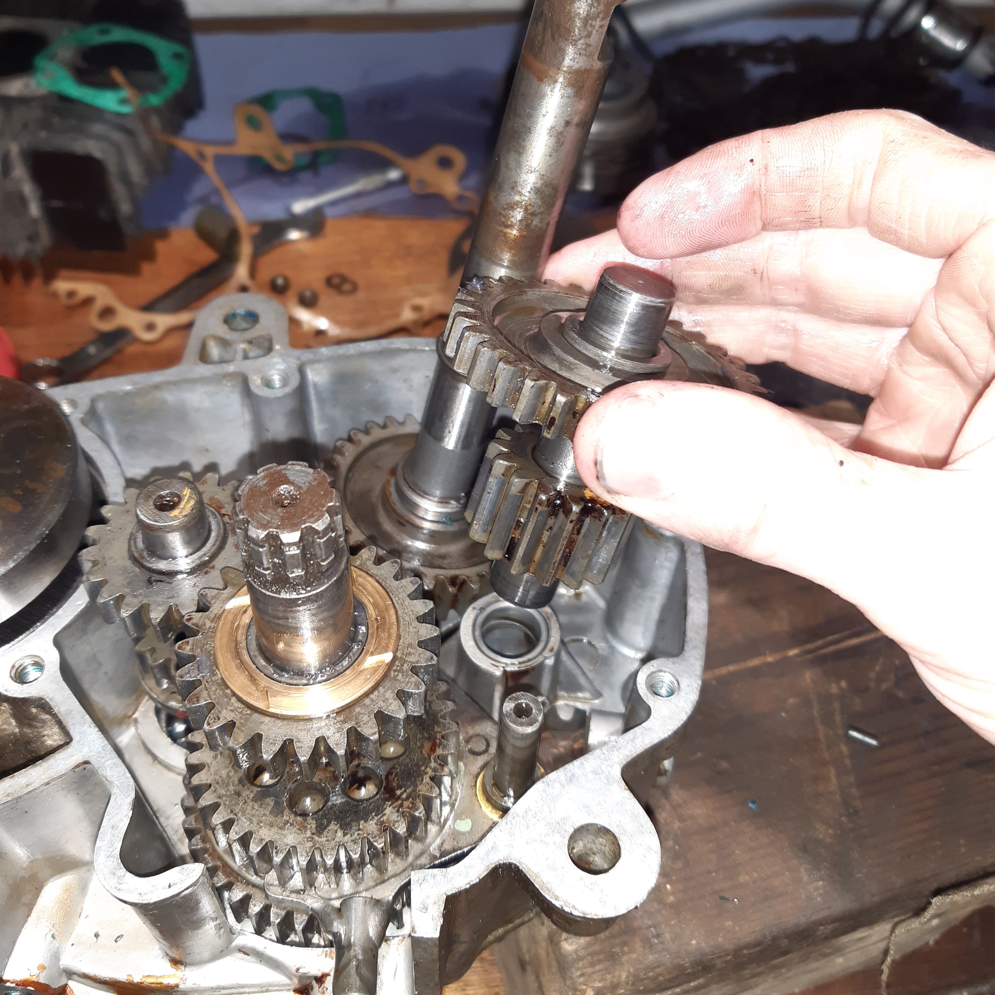
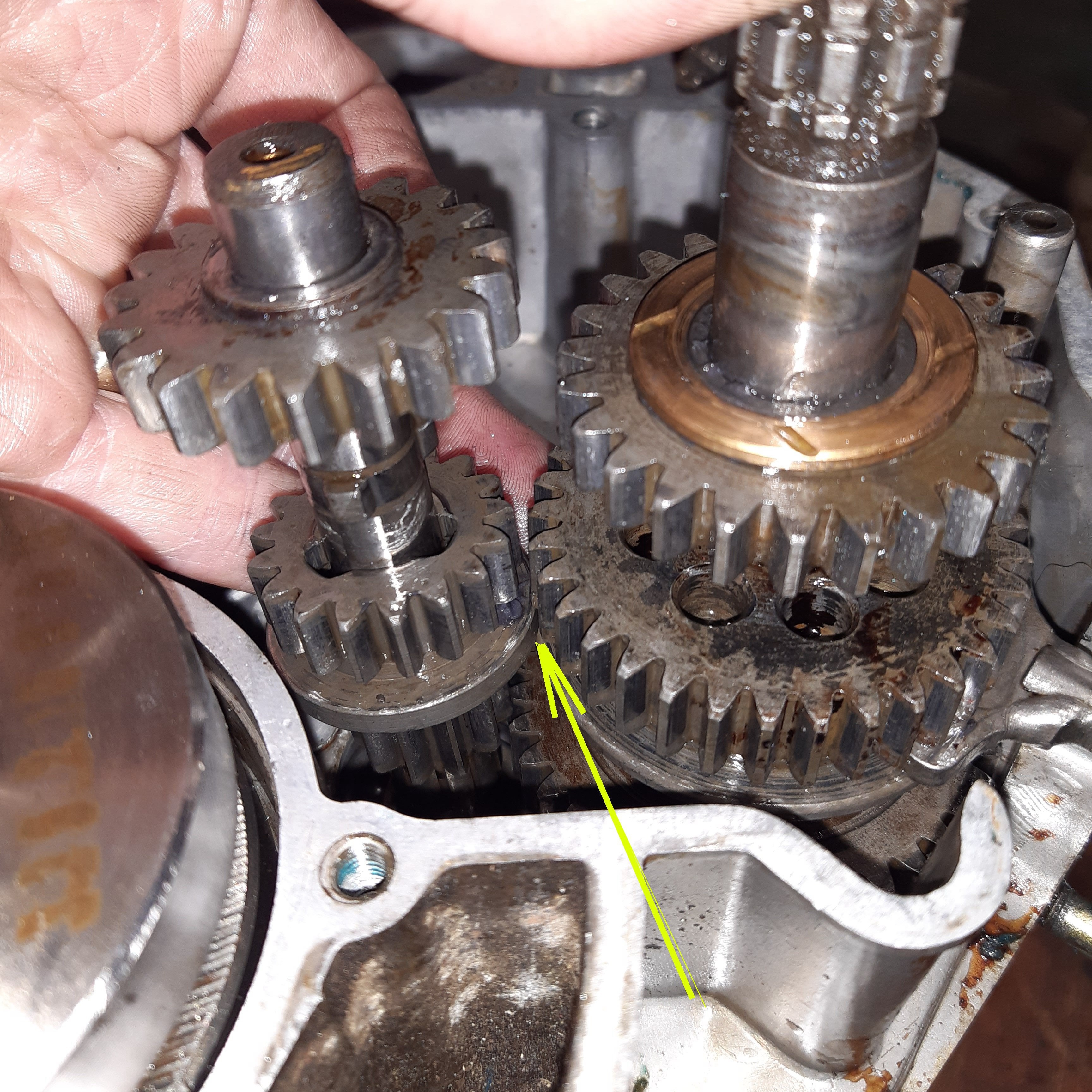
The layshaft is installed next.....
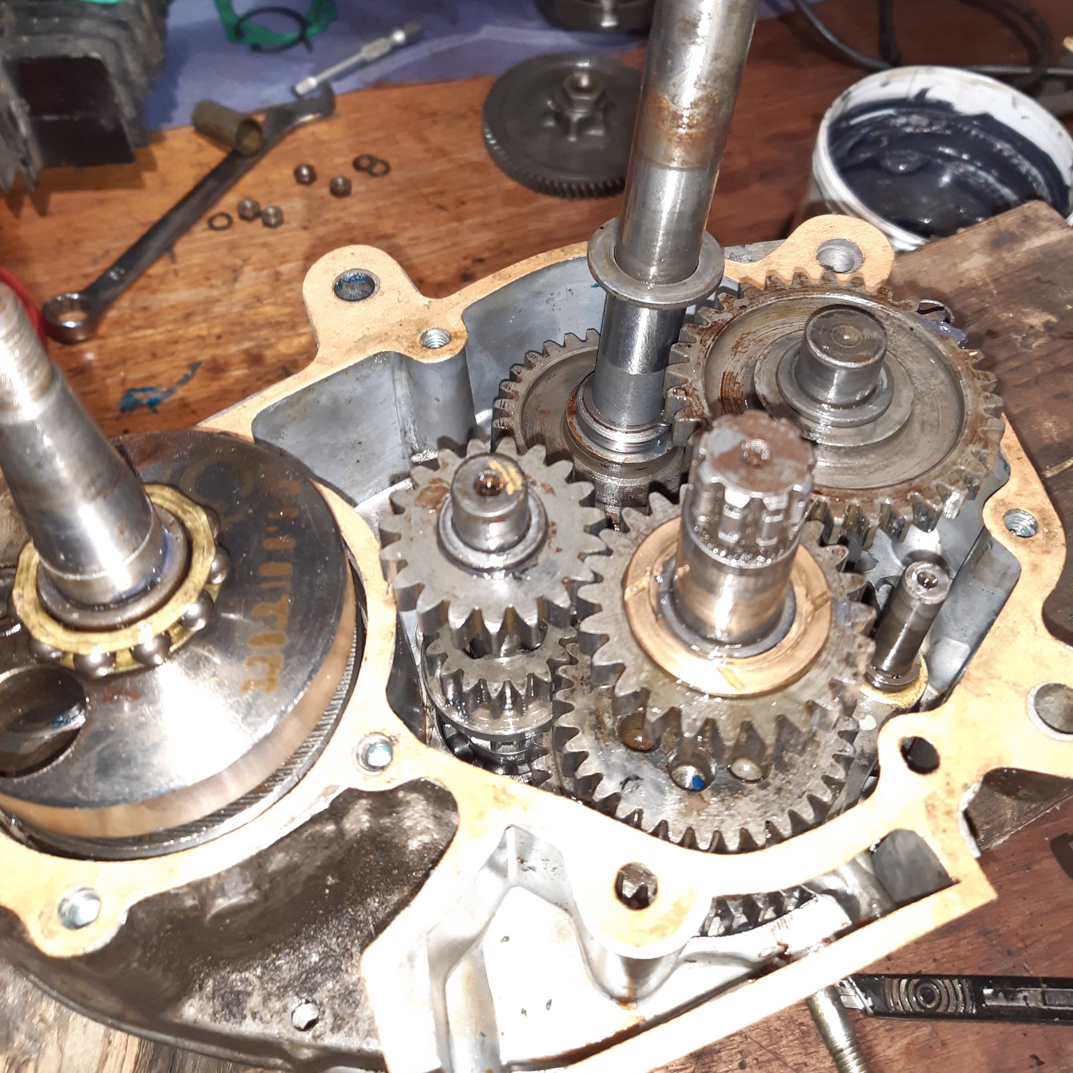
...followed by the gearbox gasket.
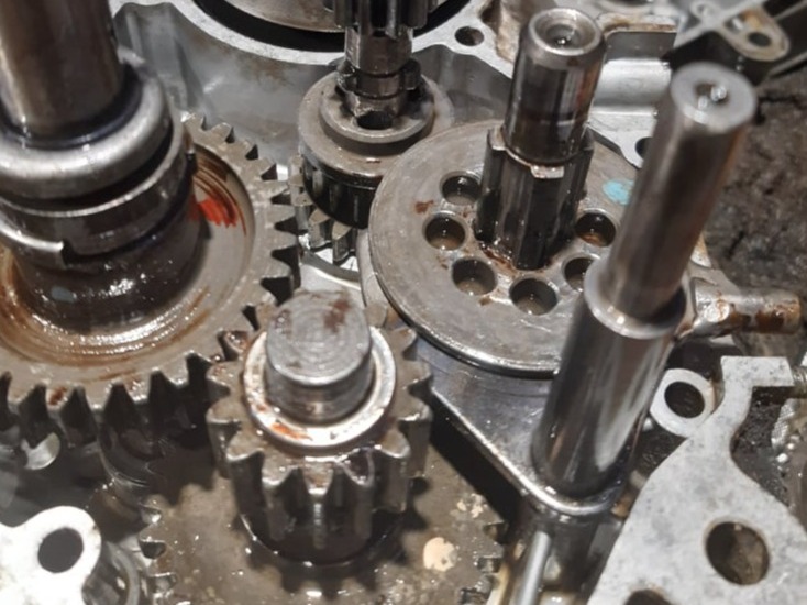
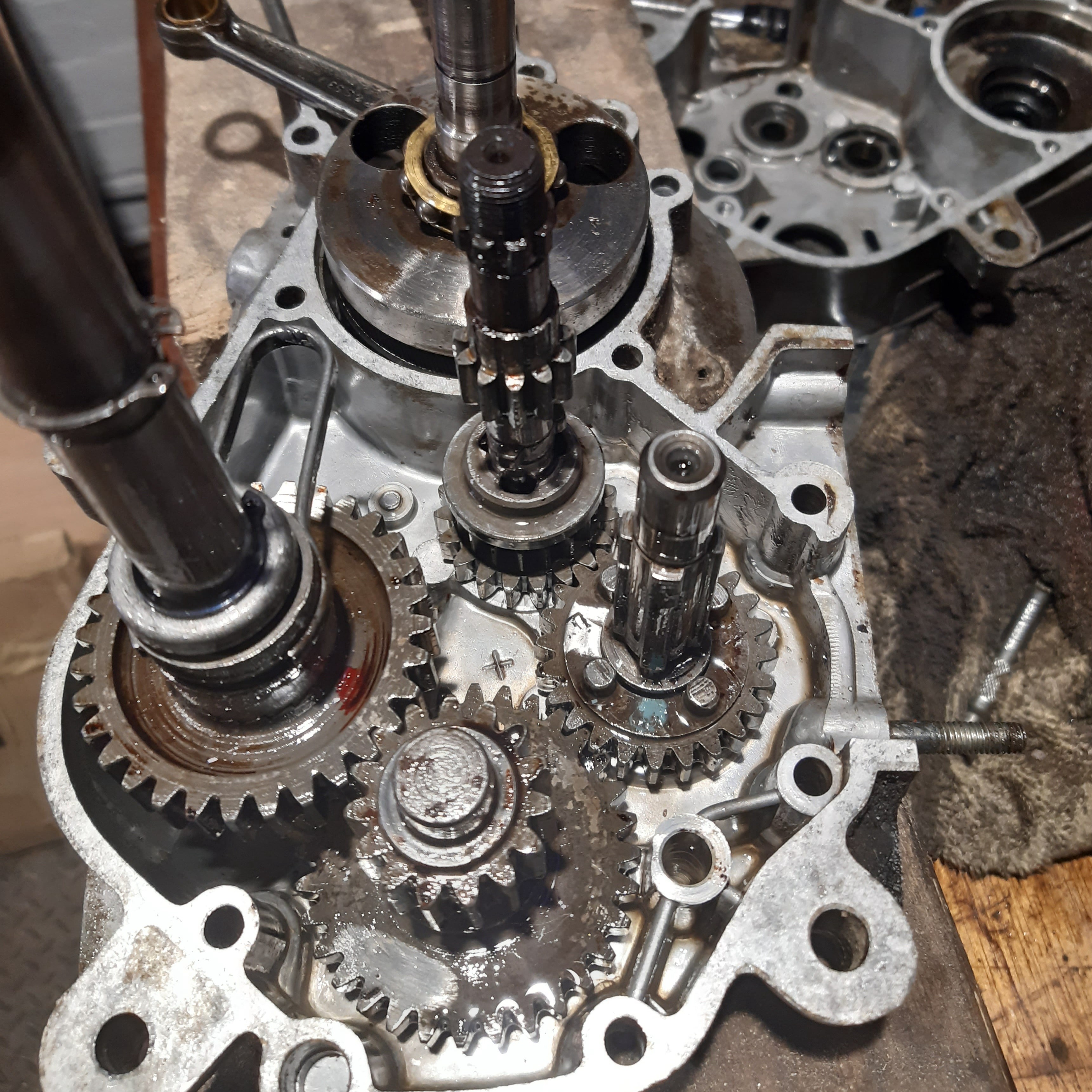
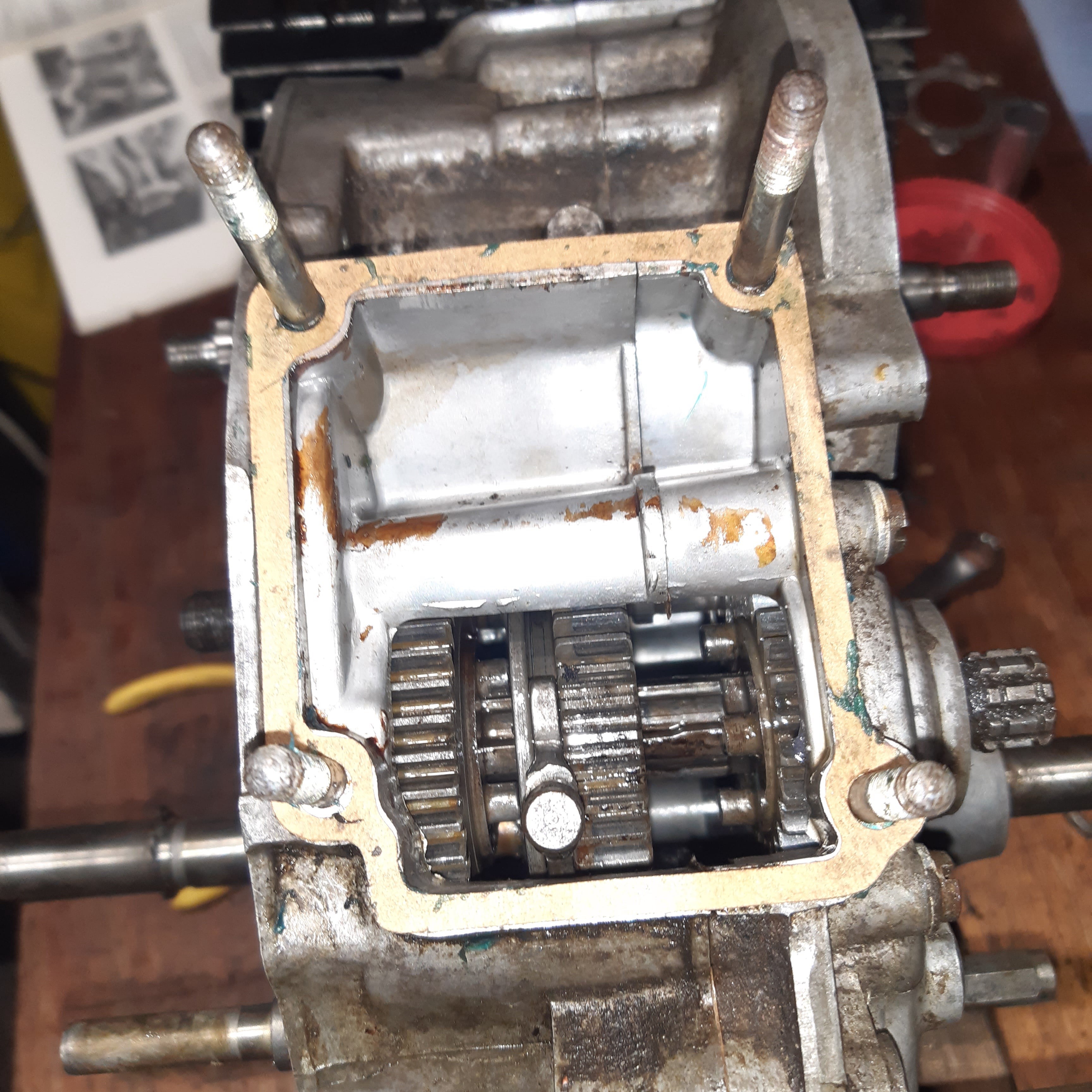
The whole cluster should look like the above.
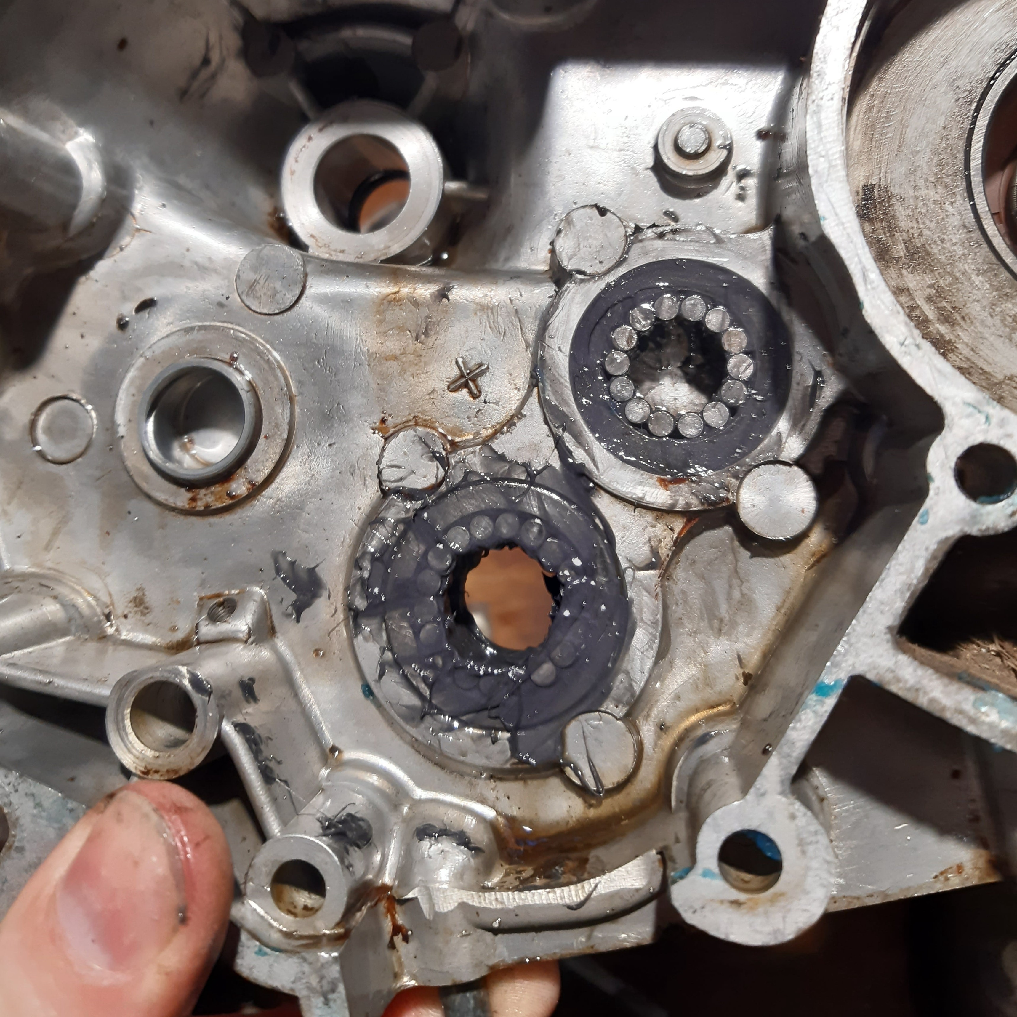
The left side of the case should be prepared with another two sets of roller bearings, one with 14 rollers and one with 18.
Care is needed to mesh the gearbox halves and then they can be secured with seven screws and two stand off bolts.
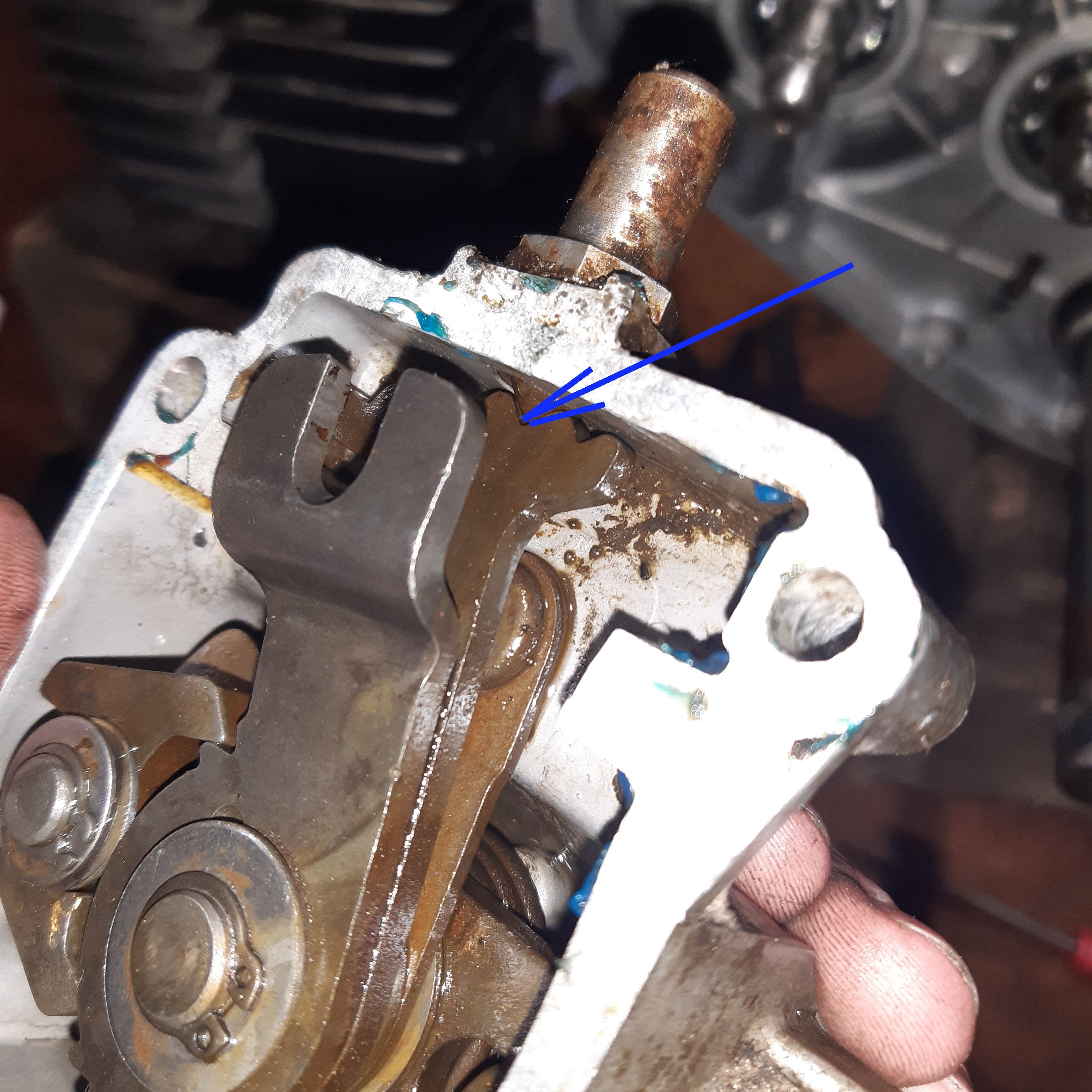
The foot change mechanism needs to be set to the neutral position before refitting the foot changer with a new gasket.
The selector is in neutral when the detent middle detent in the row of 3 that are close together, is meshed with the spring plunger.
The selector fork position shown here puts the gearbox in neutral, and now the foot changer can be bolted in with a new gasket.
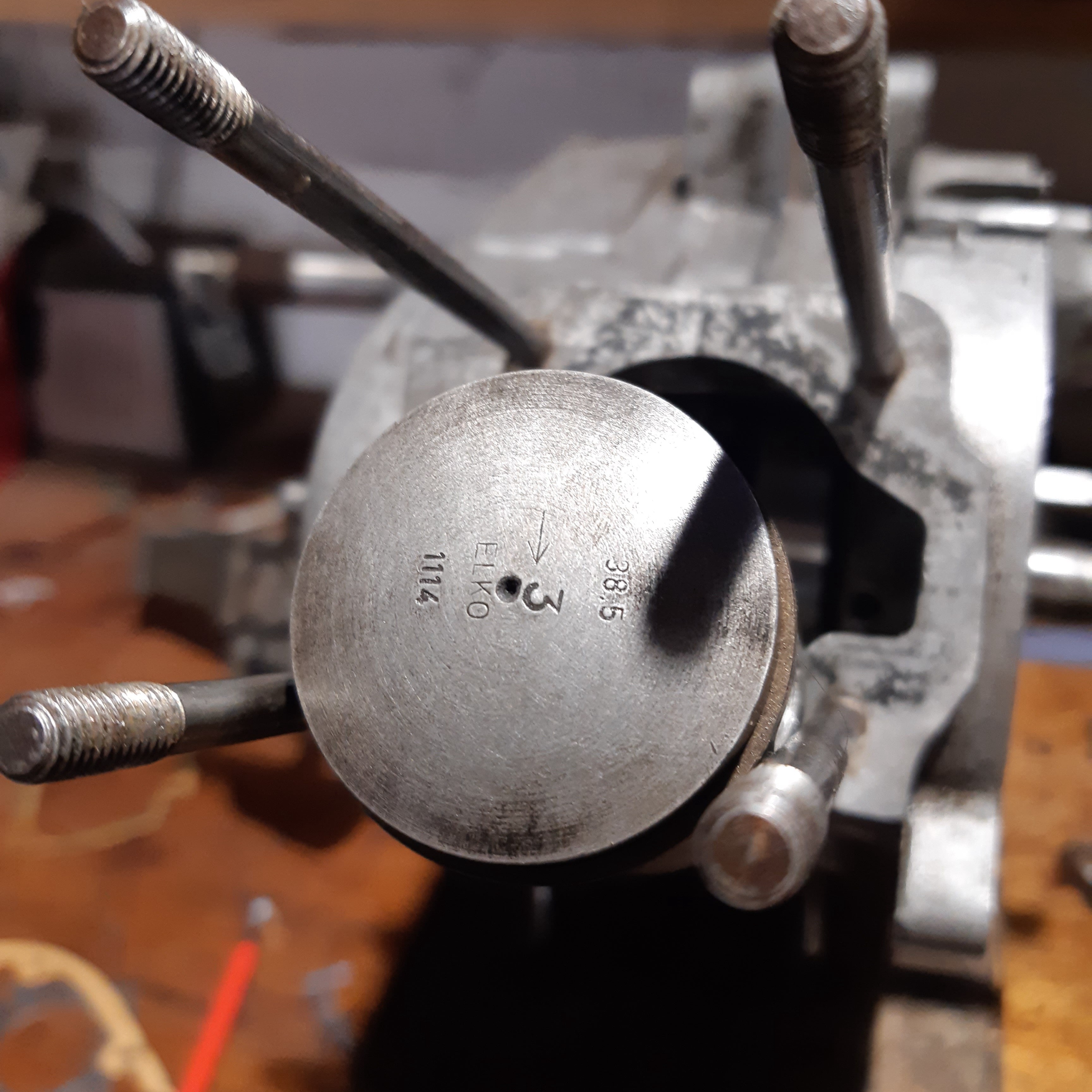
If the piston has been removed it must be replaced with the arrow pointing towards the exhaust port of the cylinder.
This image shows the correct orientation of the cylinder head, which should be fitted with a new base gasket and cylinder head gasket.
Torque for the cylinder head bolts is 7.2 ftlb
The main driving gear and clutch assembly can be replaced, and the main driving gear and clutch nut tightened.
Primary gear torque = 36.2 ftlb
Clutch centre nut = 16.6 ftlb
Then the clutch thrust bearing can be installed.
Before replacing the engine side cover, the circlip and shims need to be replaced on the pedal shaft.
As the side cover is lowered the clutch release bearing and cam mechanisms must be orientated to latch together.
On the other side of the engine, the stator, flywheel and flywheel cover were all replaced.
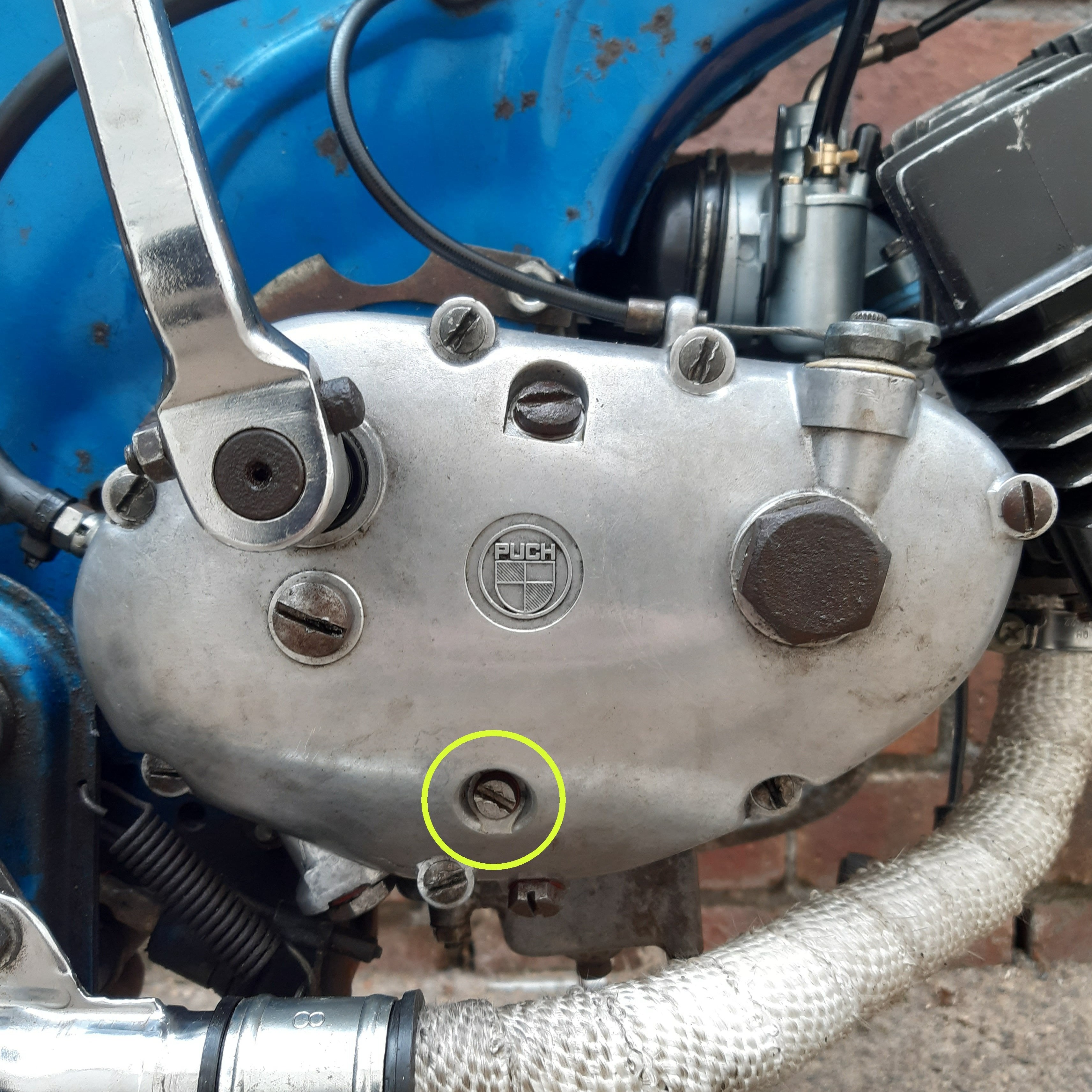
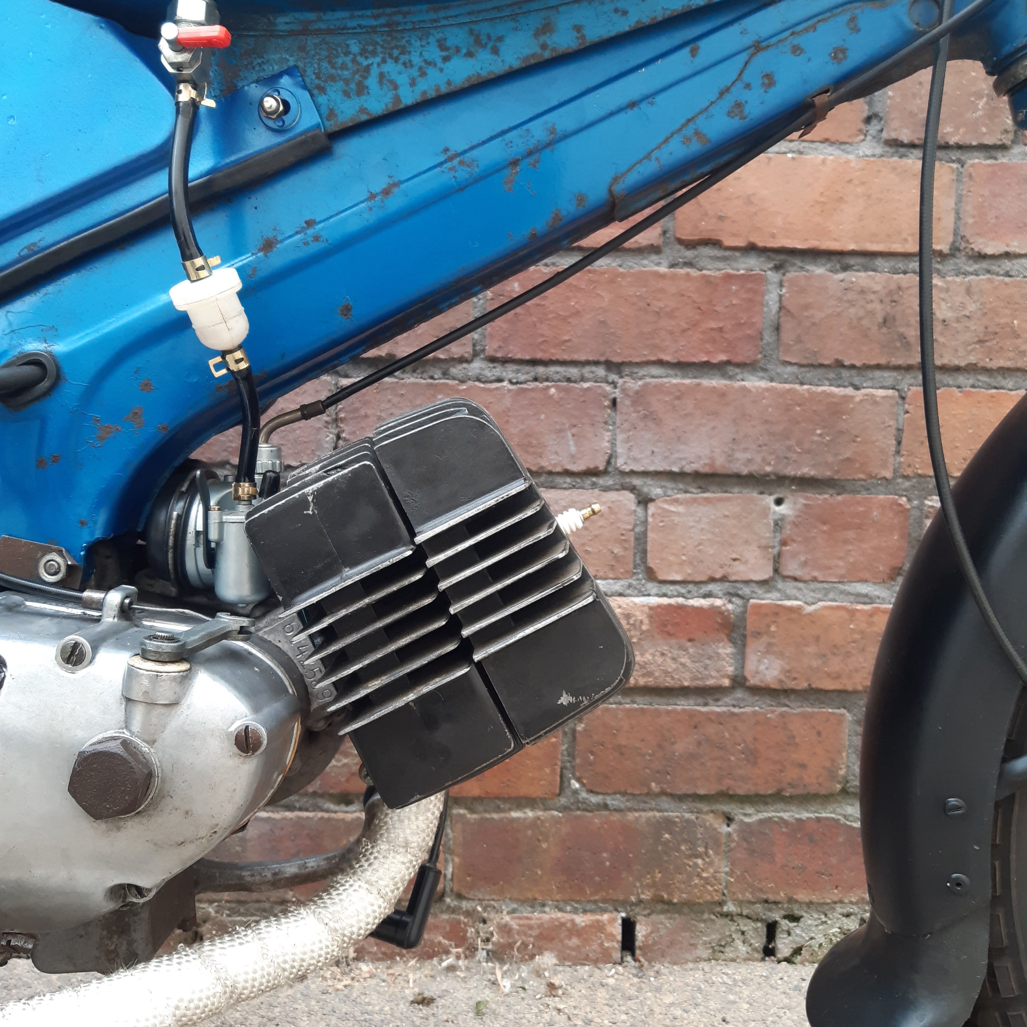
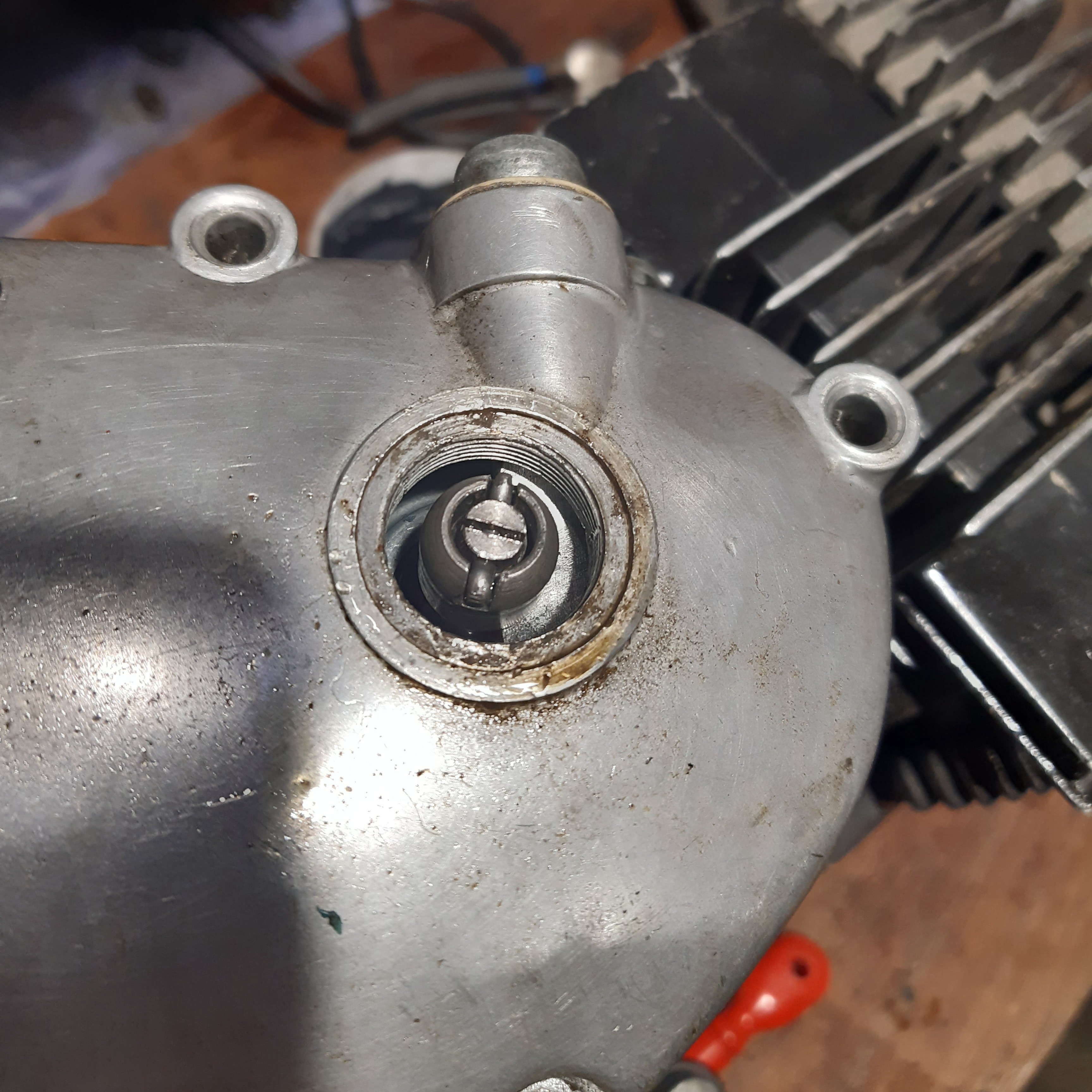
With the engine back on the bike the gearbox needs to be filled with SAE-30W gear oil until it comes out the level plug shown above.
Before starting the engine it is worth checking the timing is set correctly using the process given here.

Free AI Website Software