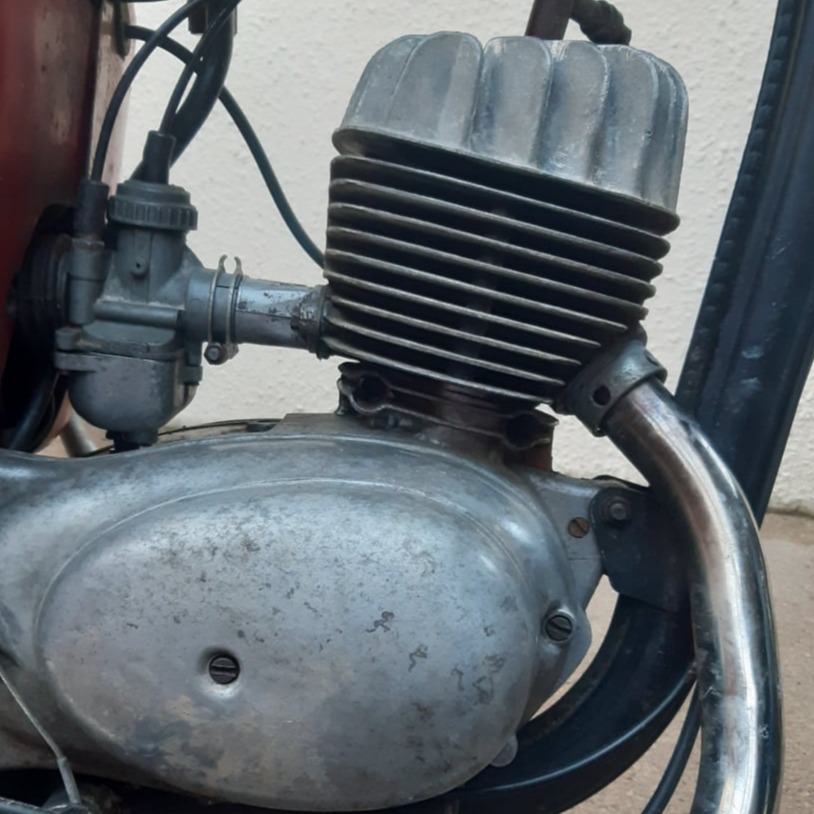
MZ TS125 Engine and Gearbox Rebuild
The engine was seized and there was evidence of water in the right hand side which had damaged the dynamo and rotor. However the gearbox oil had done a good job of preserving the gears, crank and clutch.
The engine was seized and there was evidence of water in the right hand side which had damaged the dynamo and rotor. However the gearbox oil had done a good job of preserving the gears, crank and clutch.
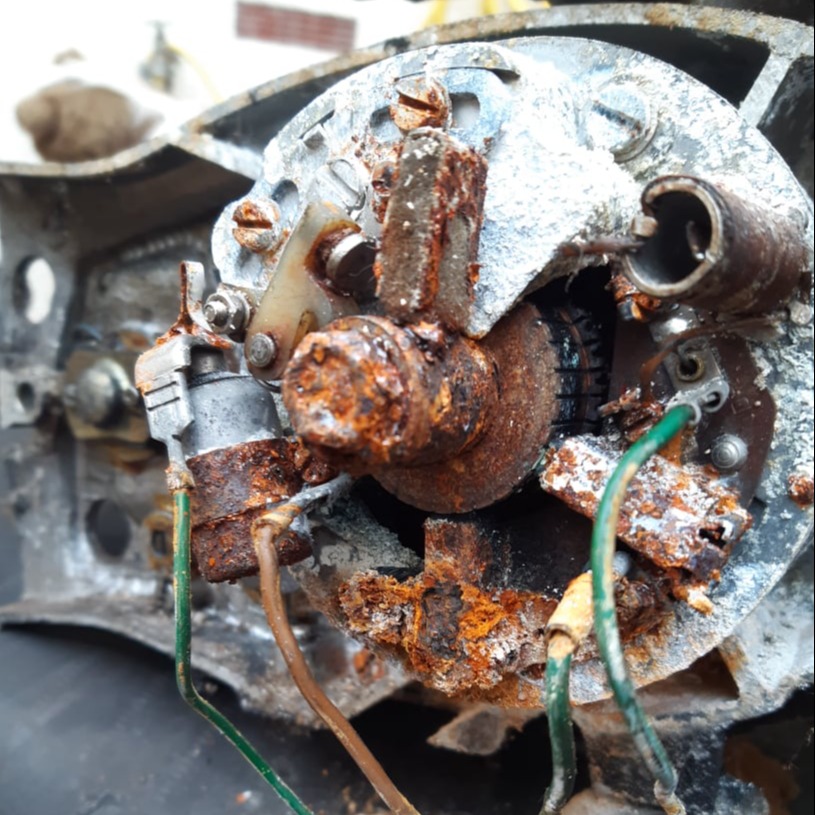
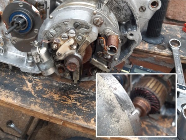
The dynamo condition is shown here. All of the electrical parts were crumbling from years of corrosion.
Fortunately the points cam was a bolt-on part and replaceable, and the rest of the crankshaft cleaned up OK.
Martin at Burwins Motorcycles, a long time spares supplier of MZ parts, helped source a good secondhand rotor and stator.
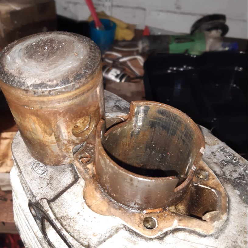
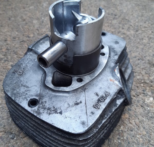
The seized piston had to be removed from the bore using a wooden drift and a hammer.
The cylinder was given to a local motor engineers for re-boring whilst an oversized piston and rings was sourced.
The rest of the engine and gearbox was stripped out and new bearings were ordered for all the gearbox shafts and the crankshaft along with any seals.
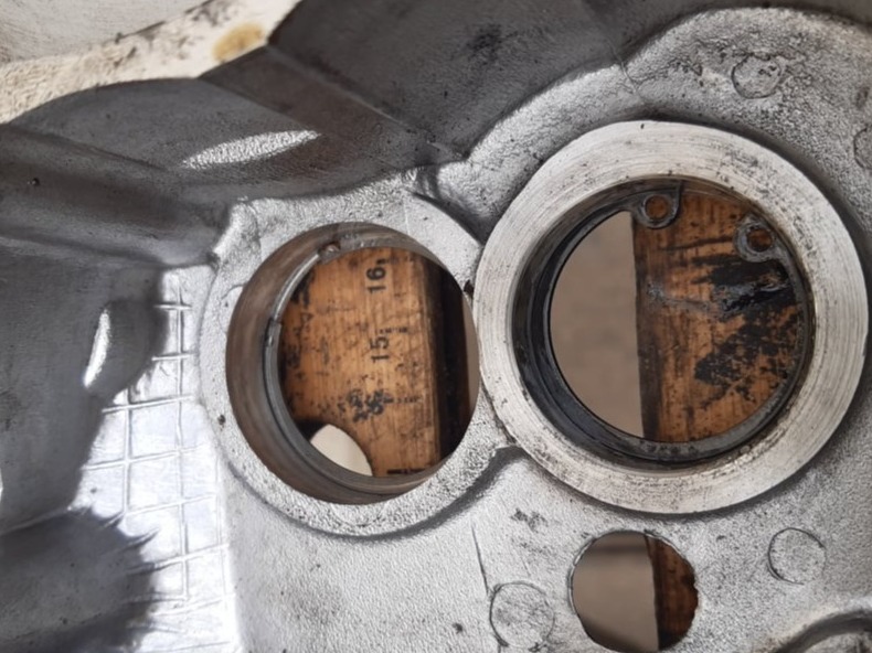
The circlips and bearing shims for the two gearbox shafts were placed in the left hand engine case.
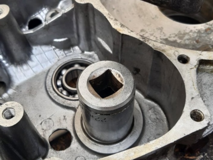
With the engine case warmed up, both bearings for the gearbox shafts were installed
Top bearing as shown here is 6202 C3 15mmx35mmx11mm
Lower one is 6201 C3 12mmx32mmx10mm
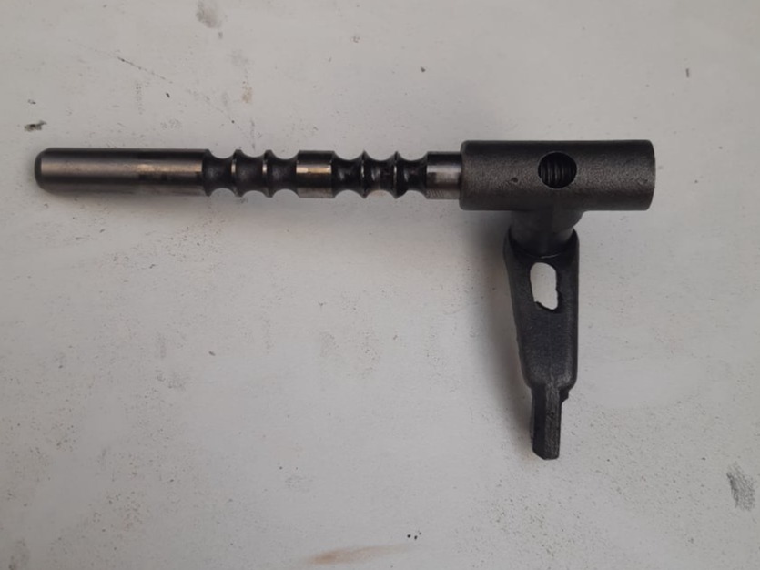
The selector fork was positioned as shown on the selector rod, this position equates to 4th gear
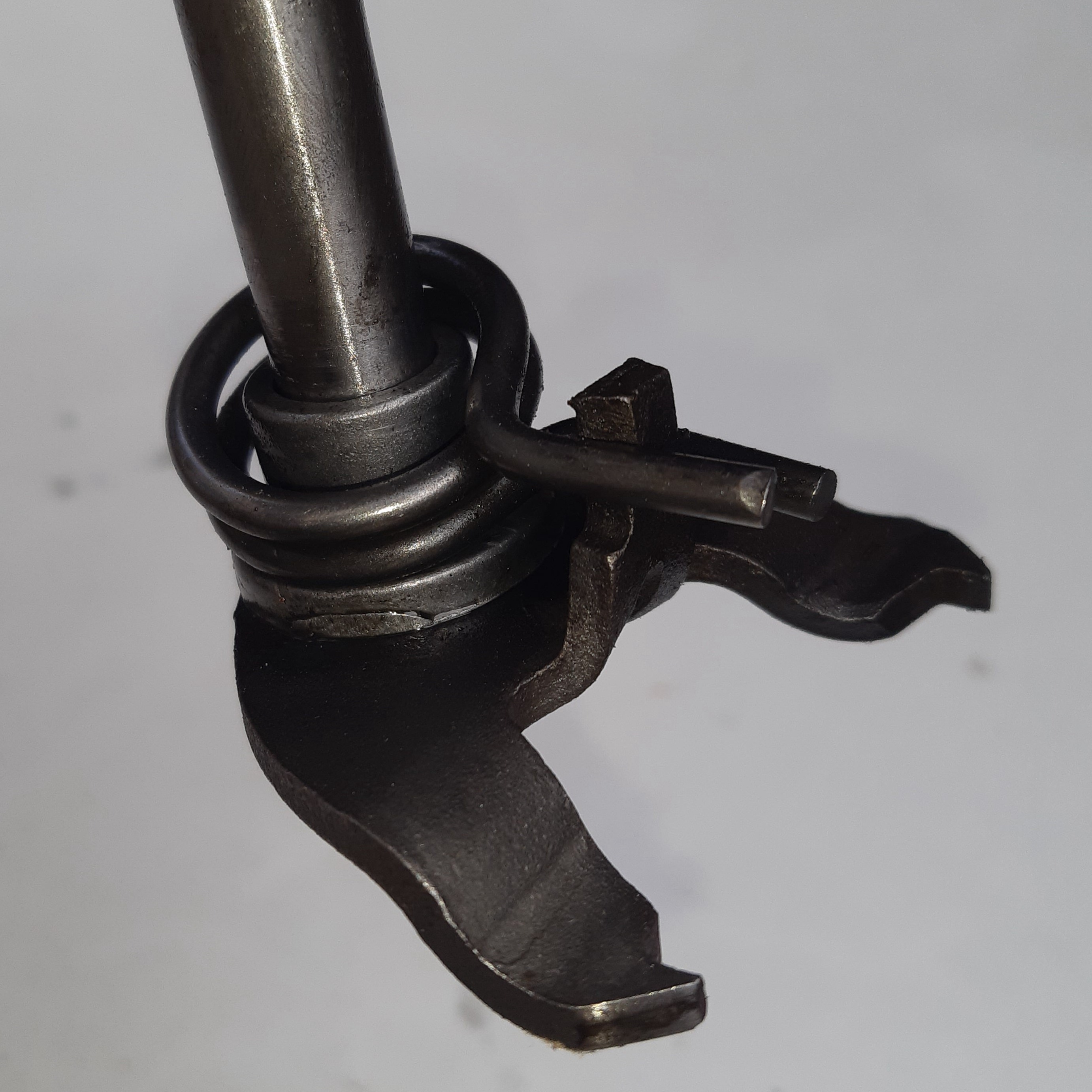
The selector shaft return spring was located as shown.
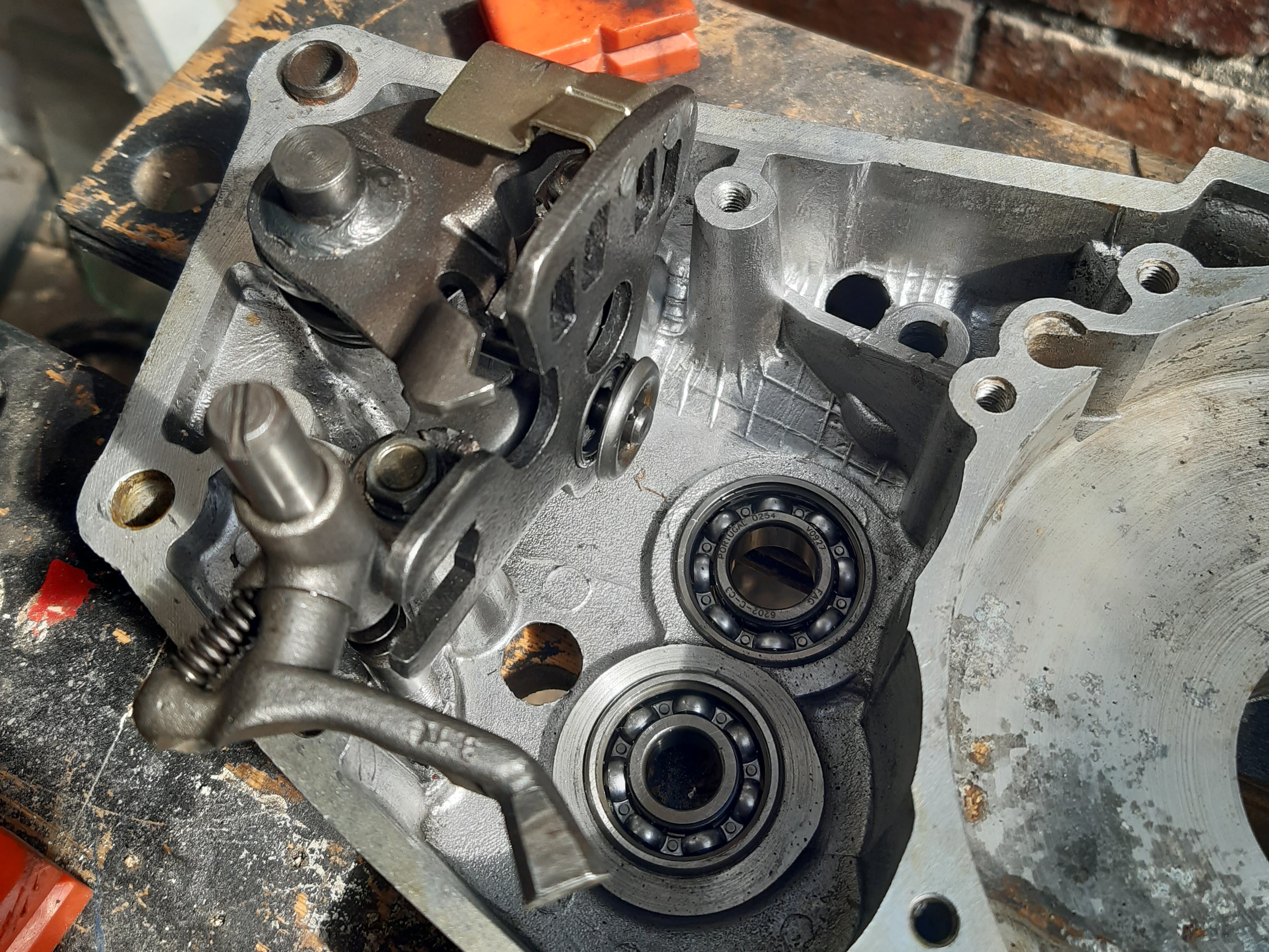
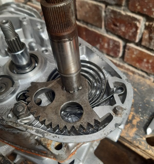
The gearbox selector components were place in to the left side housing including the quadrant gear which was positioned as shown for 4th gear.
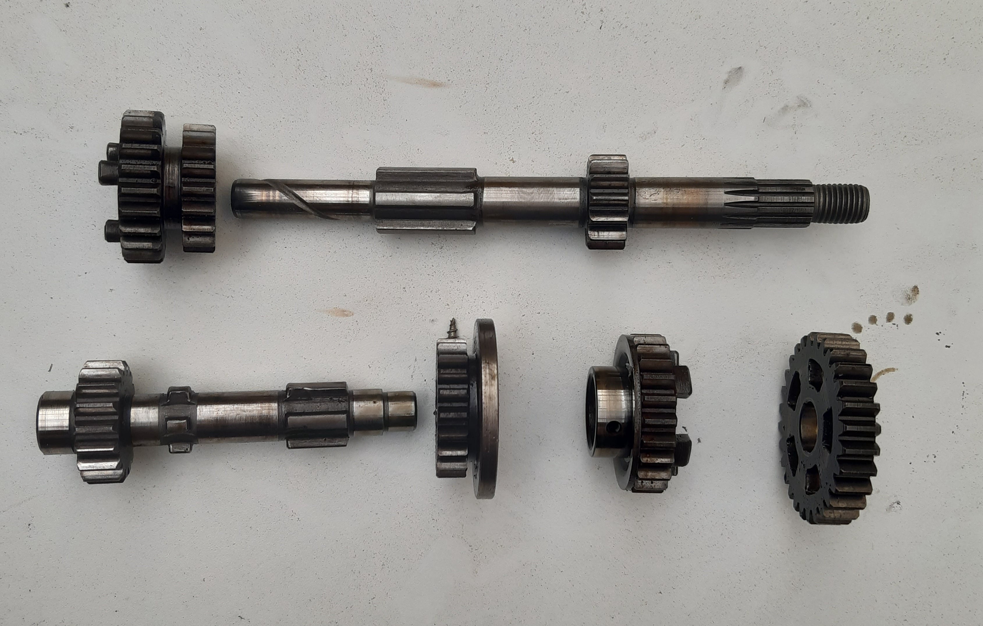
The gearbox components were positioned on the shafts as shown above.....
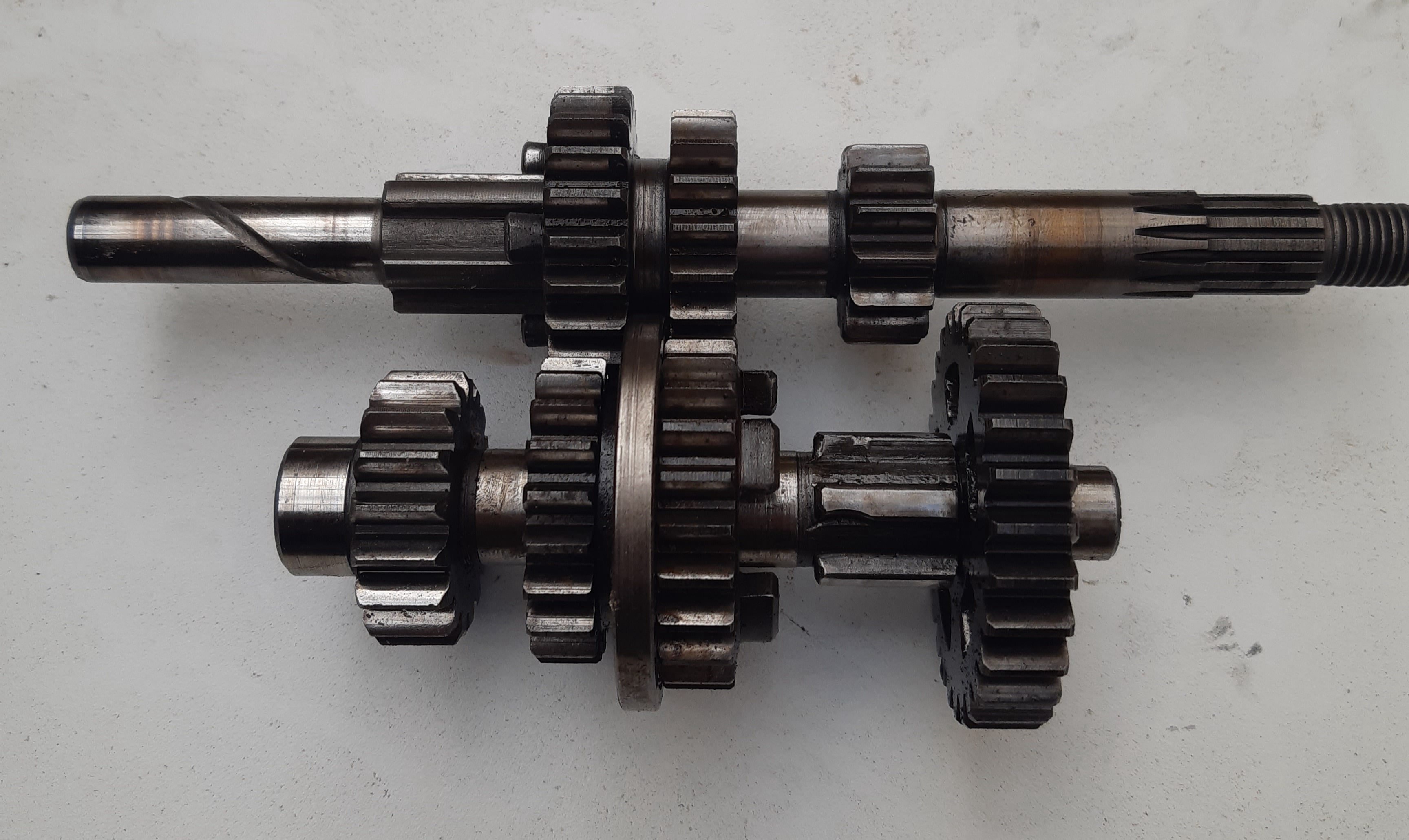
......and assembled like this.
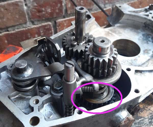
Both gearbox shafts were lowered into the bearings and the selector fork engaged with the gears
Note that this photo show a first attempt when the gear shown had dropped down the shaft. This is incorrect, the gear should be held up against the others during install.
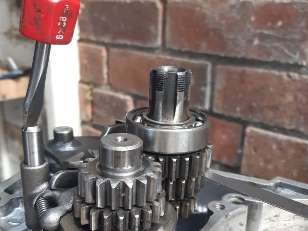
With top gear engaged, the gap between the main shaft gears was checked and adjusted to be 0.2mm using feeler gauges.
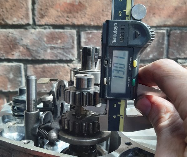
The gearbox was shifted into 3rd gear and the gap shown checked to be 13mm. In both cases the selector rod was screwed in or out to find the best compromise for this, and the previous measurement.
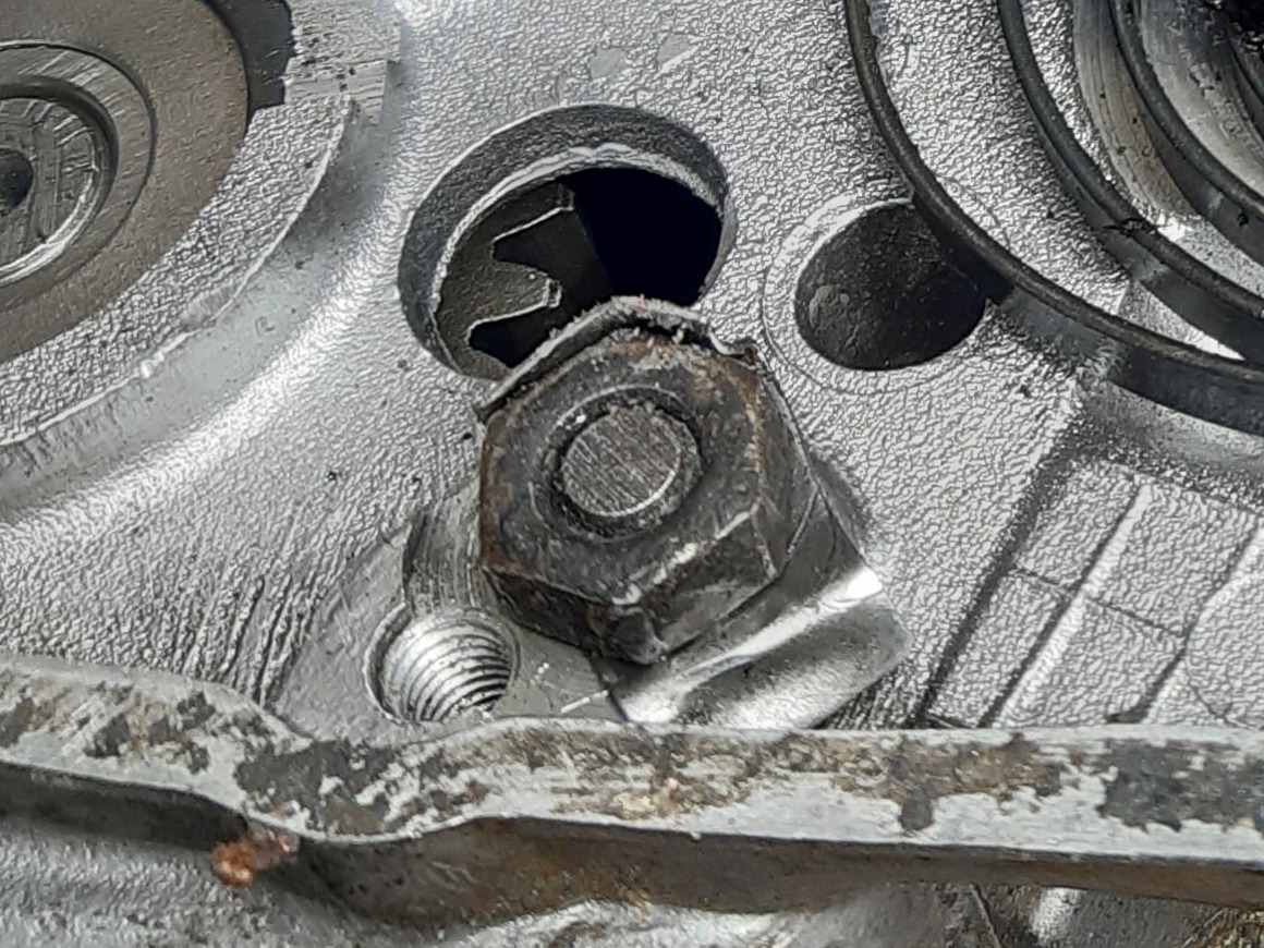
Once set, the lock nut was secured to the selector rod and held with the tab plate.
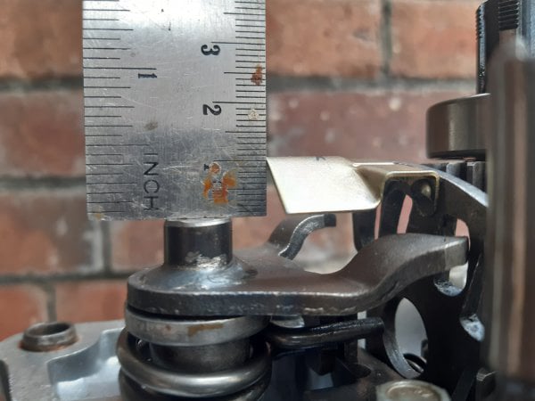
With the gearbox shifted into neutral the gap from the end of the selector shaft to the neutral light plate was checked to be 11mm. The plate was bent as needed.
The crankshaft was prepared with its bearings.
Two bearings on the drive side: 6204 20mmx47mmx14mm
The single bearing on the other side: 6304 20mmx52mmx15mm
These bearing types are applicable to the later MM/3 engine. The whole crank assembly was then placed in the freezer.
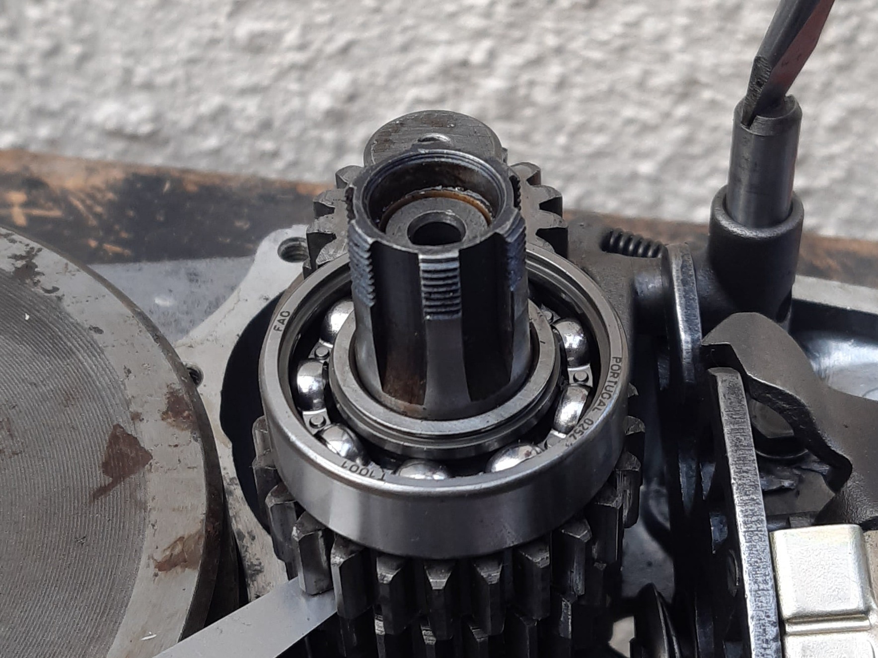
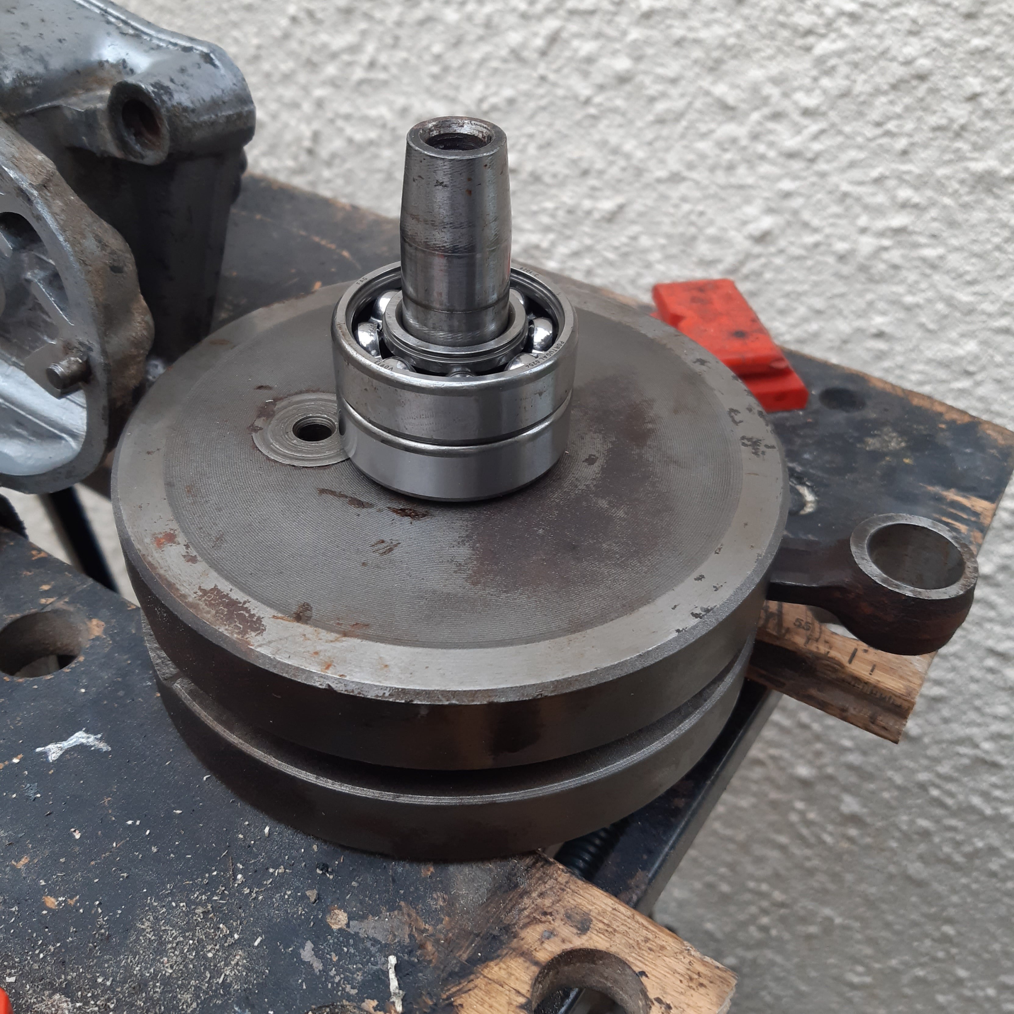
The output shaft was put into place and fitted with bearing 6004 15mmx35mmx11mm
The main crank circlip was re-installed
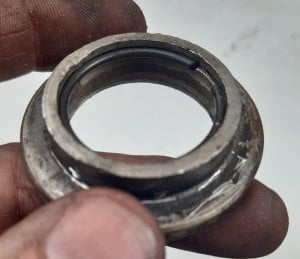
The main crank seal was prepared as shown....
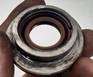
.......(note the orientation).......
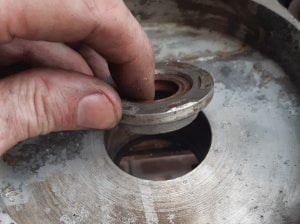
.....and drifted into the left side cover.
The right side engine cover was prepared for assembly by heating with a hot air gun.
Then the crank was removed from the freezer and dropped into the left side case.
The warmed right side case was then added with some sealant between the halves.
Unfortunately there are no photographs of this step because I had to move quickly and had no spare hands 😐
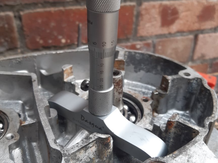
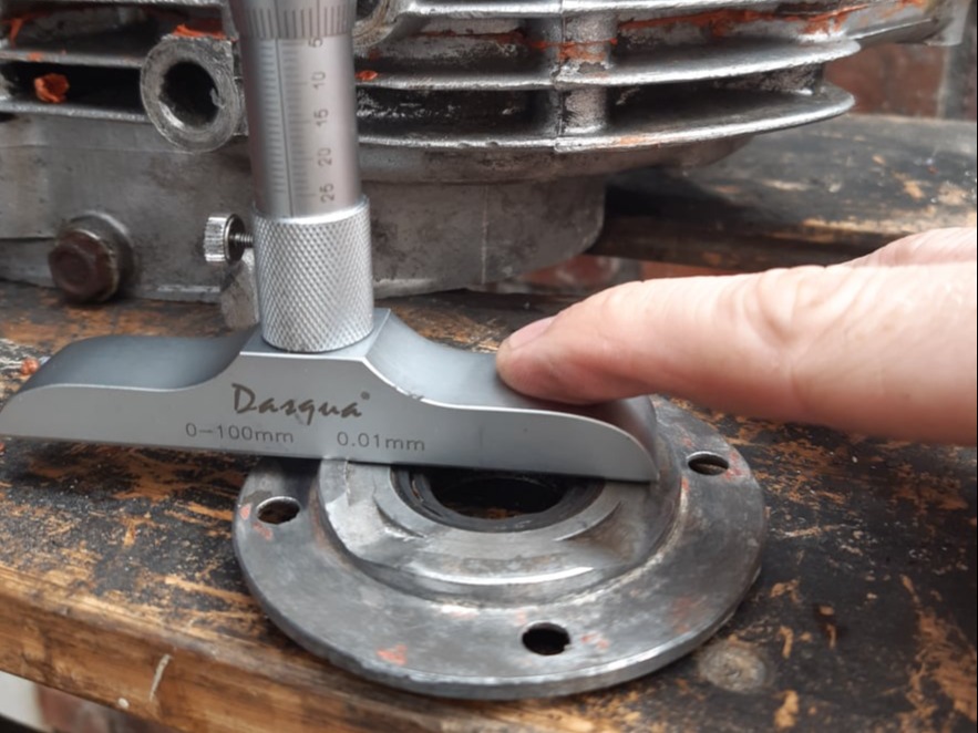
The depth of both the main crank bearing and the output shaft bearing were checked with a micrometer and adjusted with shims to give 0.2mm-0.3mm end float.
Main bearing shims = depth of bearing + gasket thickness + clearance - housing shoulder (see next photo)
Output shaft shim = Depth of bearing + gasket thickness + clearance.
Checking main bearing housing shoulder.
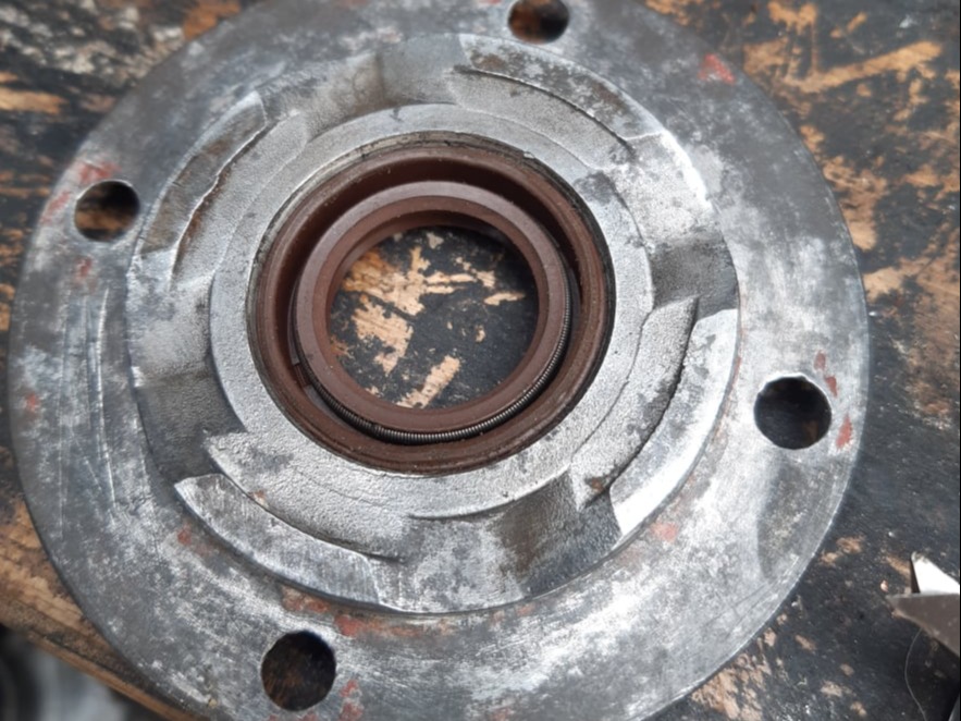
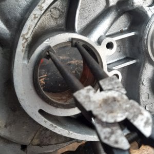
Both the main crank seal...........
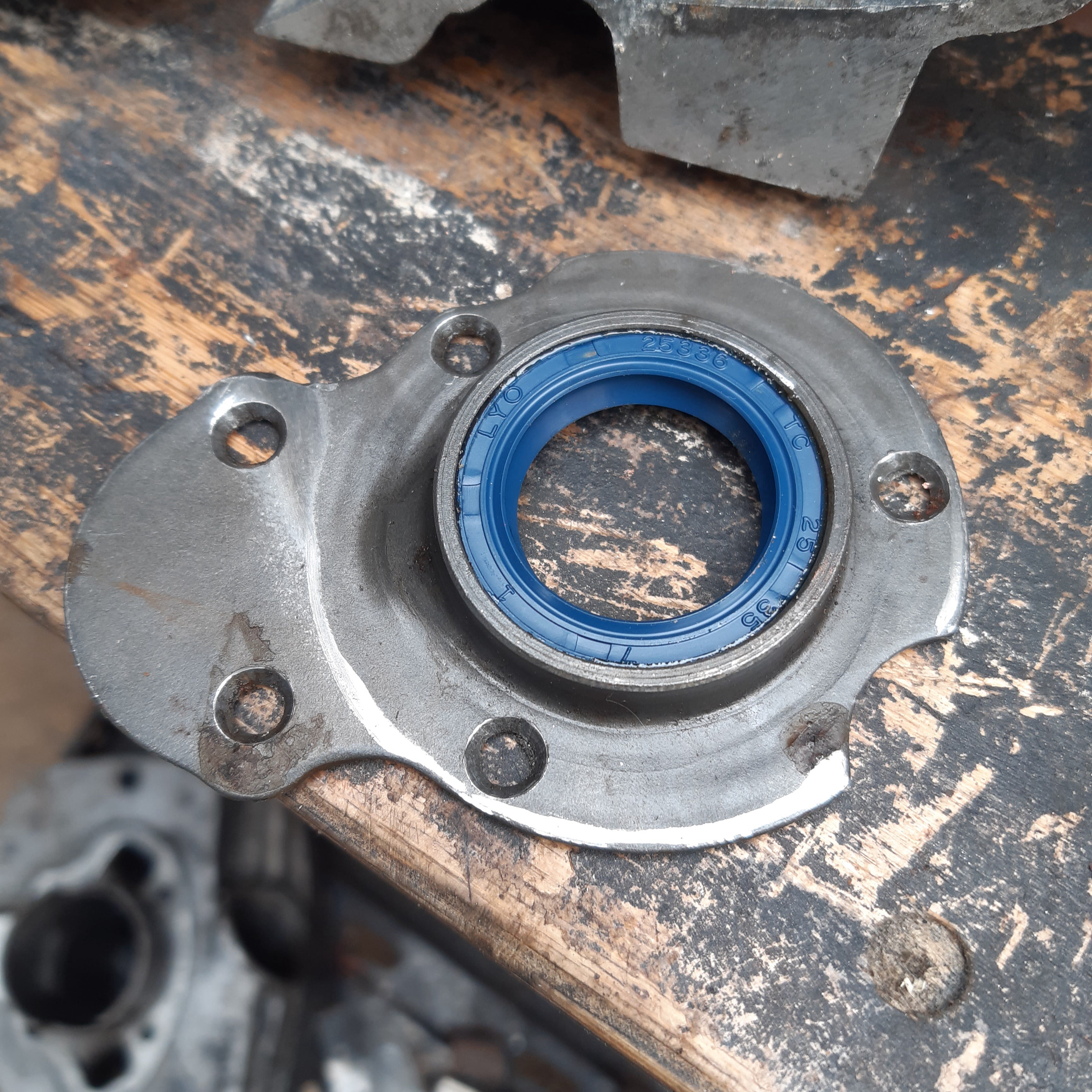
......and the output shaft seal were prepared in their housings and then screwed into place with a gasket.
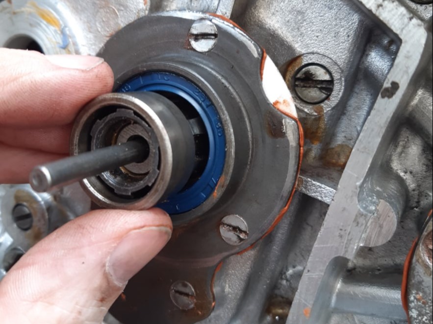
The clutch push rod and output shaft spacer were installed.
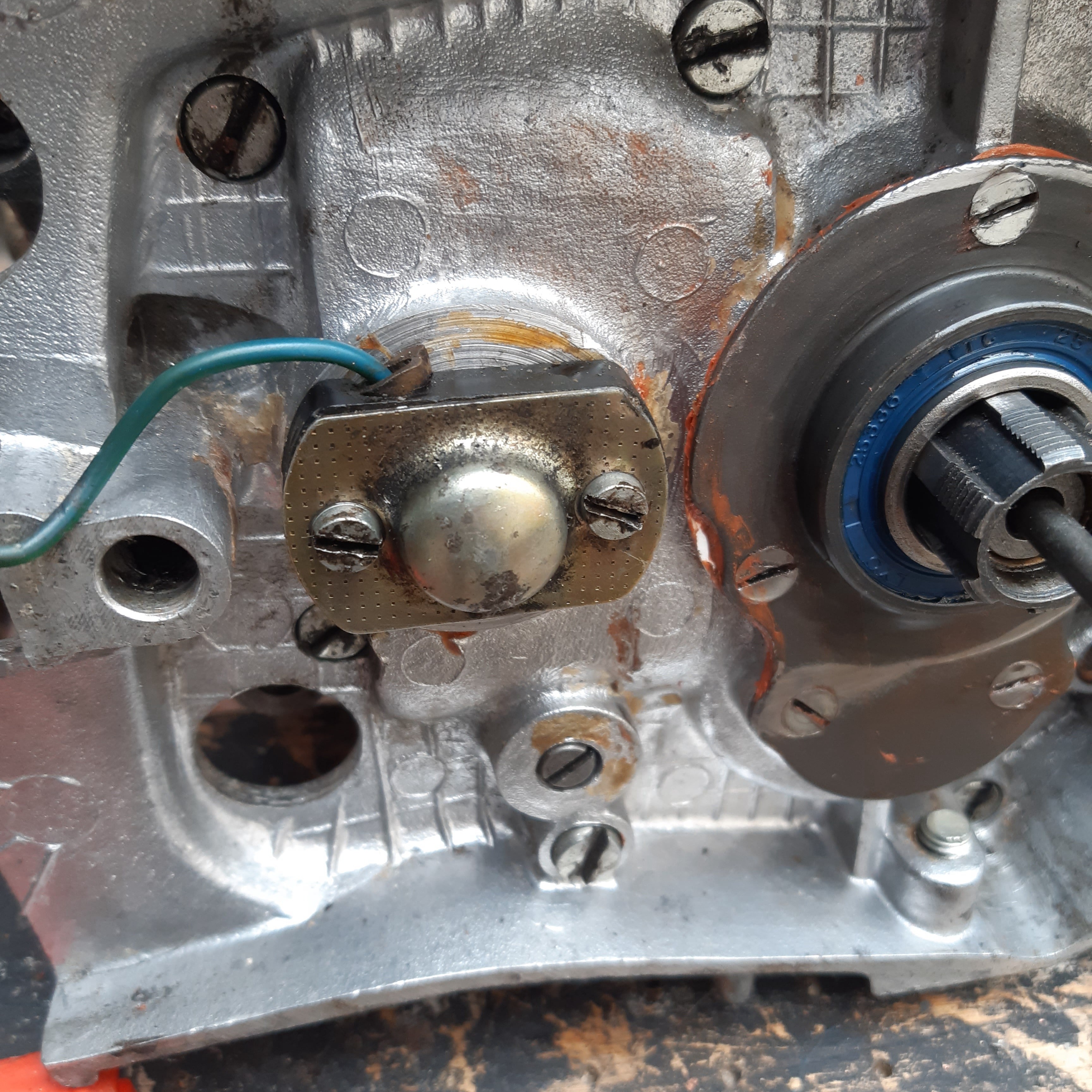
The neutral switch was screwed into place and adjusted.
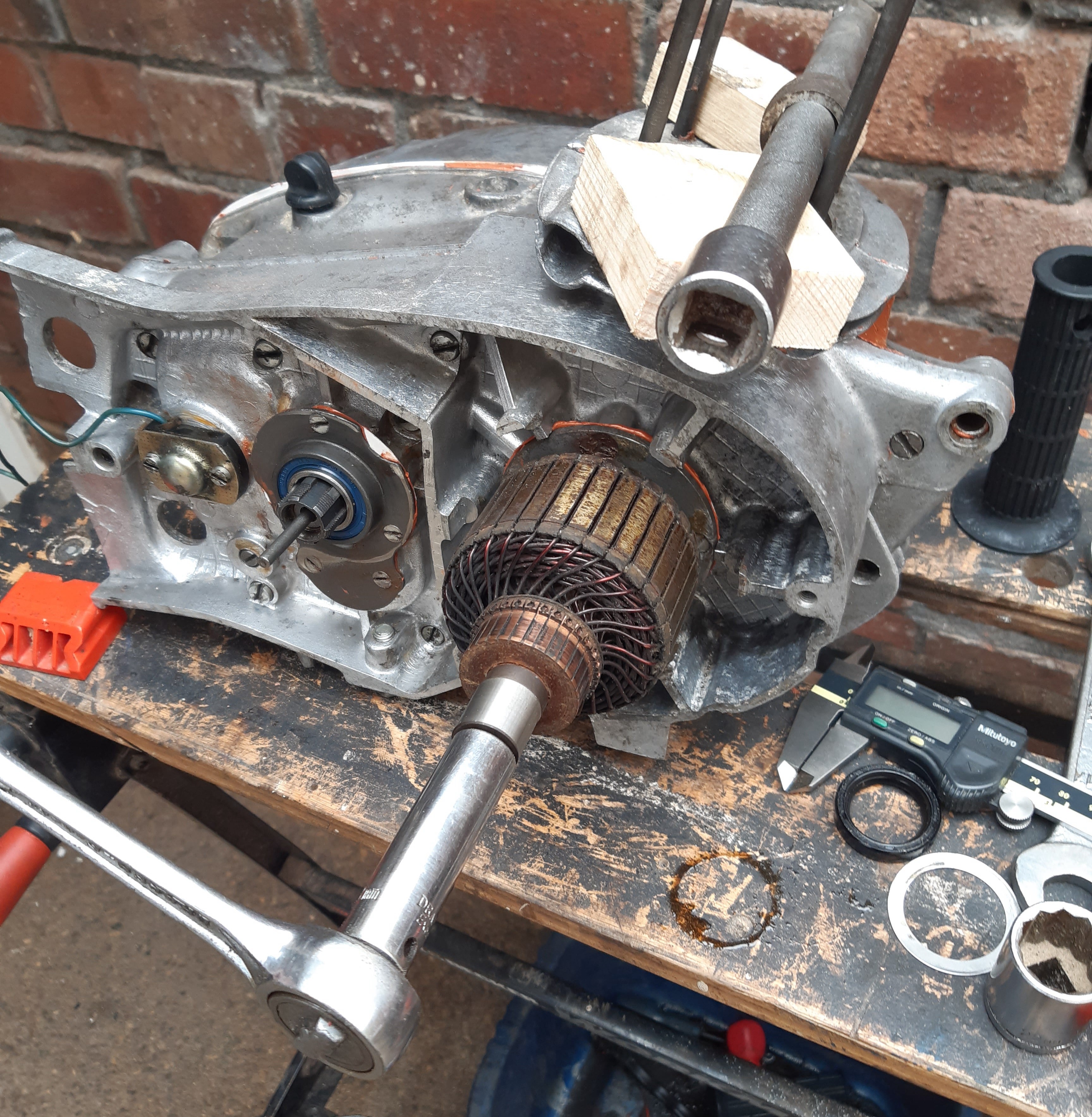
With the conrod held as shown the generator rotor and points cam were secured to the crankshaft
The generator housing was installed ensuring the slot (inset) located on the dowel in the main engine case.
The carbon brushes were retracted during this process to avoid damage.
The piston was fitted with new rings and installed in the cylinder using finger pressure to compress the rings.
The arrow on the top should face the exhaust port in the cylinder.
The gudgeon pin was put in the freezer, to make it contract before fitting.
The cylinder and piston were aligned with the con rod and the gudgeon pin pushed home and secured with new circlips.
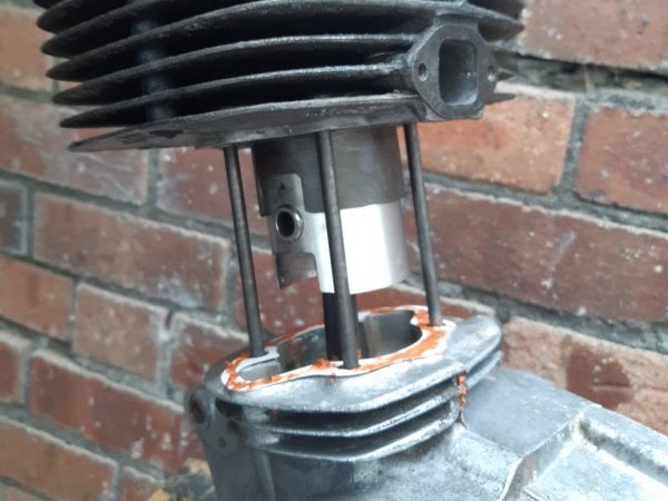
Then the cylinder was pushed down to seat on a new base gasket.
The kick start quatrant was replaced including any shims that were behind it and with the spring engaged as shown.
Note that this photo shows the spring without tension. A full clockwise turn was made after this position to get the spring tension correct.
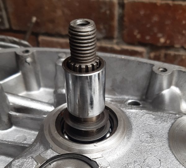
The clutch bush and any shims were placed on the input shaft.
If the shims need recalculating then both primary drive sprockets should be assembled to the engine and any misalignment of the chain checked with a straight edge.
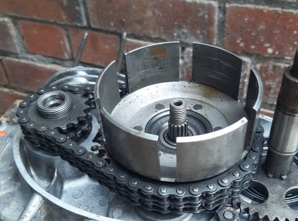
The clutch basket and primary gear were positioned onto their shafts.
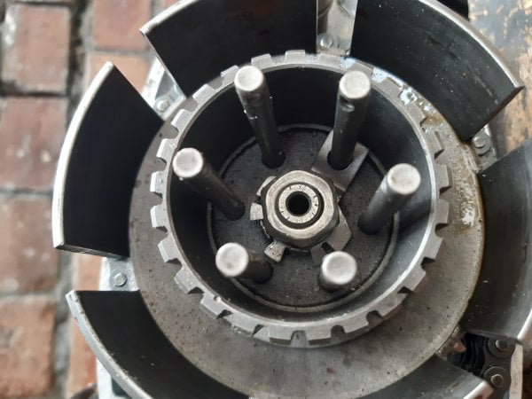
The clutch centre nut was tightened (left handed) and then secured with a tab from the locking washer.
Specified torque = 58Nm - 68Nm
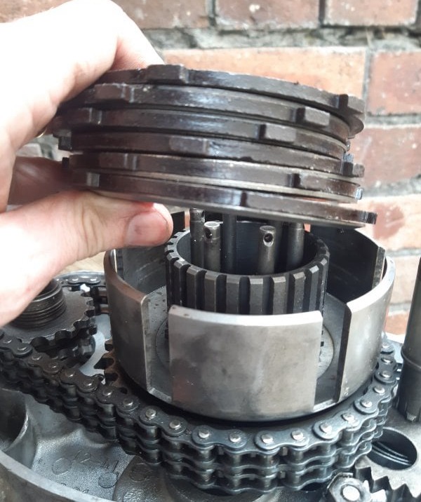
The clutch plates were replaced as shown with the thicker plain plate at the bottom, with the beveled face lower most......
.....followed by the clutch push rod.
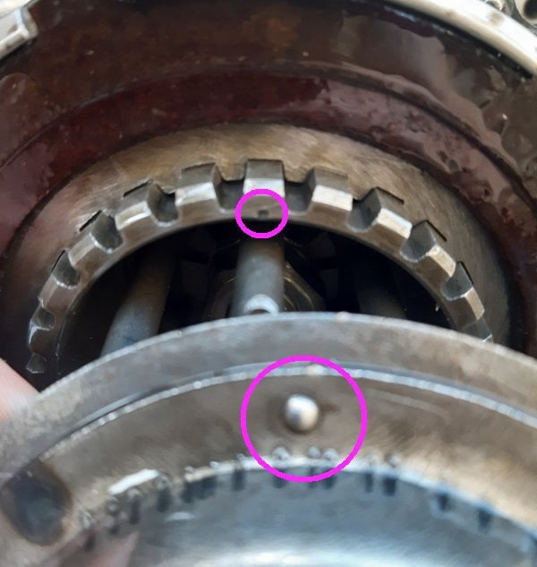
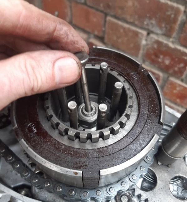
The clutch cover was fitted making sure the highlighted features were aligned.
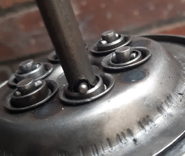
Each clutch spring was compressed with a notched tube and the locking pins put in one by one
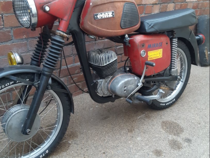
The engine was put back in the frame and the external covers refitted with gaskets, and the control levers attached.

HTML Website Creator