Rebuilding the Honda S90 Wheels
The Honda wheel rims and spokes were corroded.
This page shows how they were rebuilt using some home-made jigs and some new parts.
The Honda wheel rims and spokes were corroded.
This page shows how they were rebuilt using some home-made jigs and some new parts.
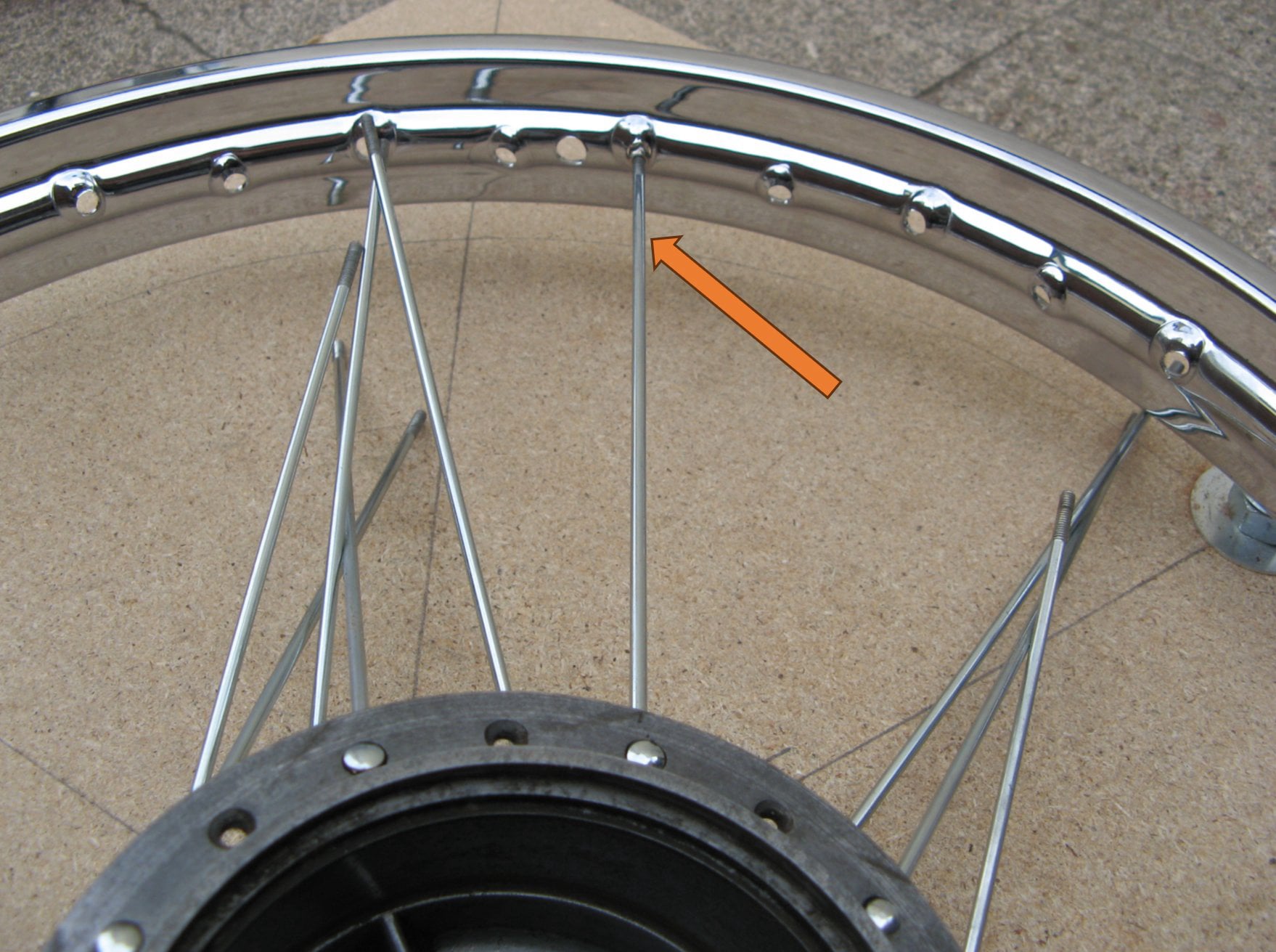
Each wheel contained 36 spokes, but with 2 different spoke head angles used.
The rim had 36 holes to match (obviously) but there were 4 different angles of hole.
Spoke quantity = 36.
Spoke length = 196mm
Different spoke types = 2.
Rim hole quantity = 36
Rim hole types = 4
Valve hole = 1 (reference point).
Both wheels on the S90 were identical, but fitted with different hubs; so during the rebuild one wheel was kept complete as a pattern to build the other.
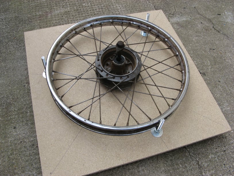
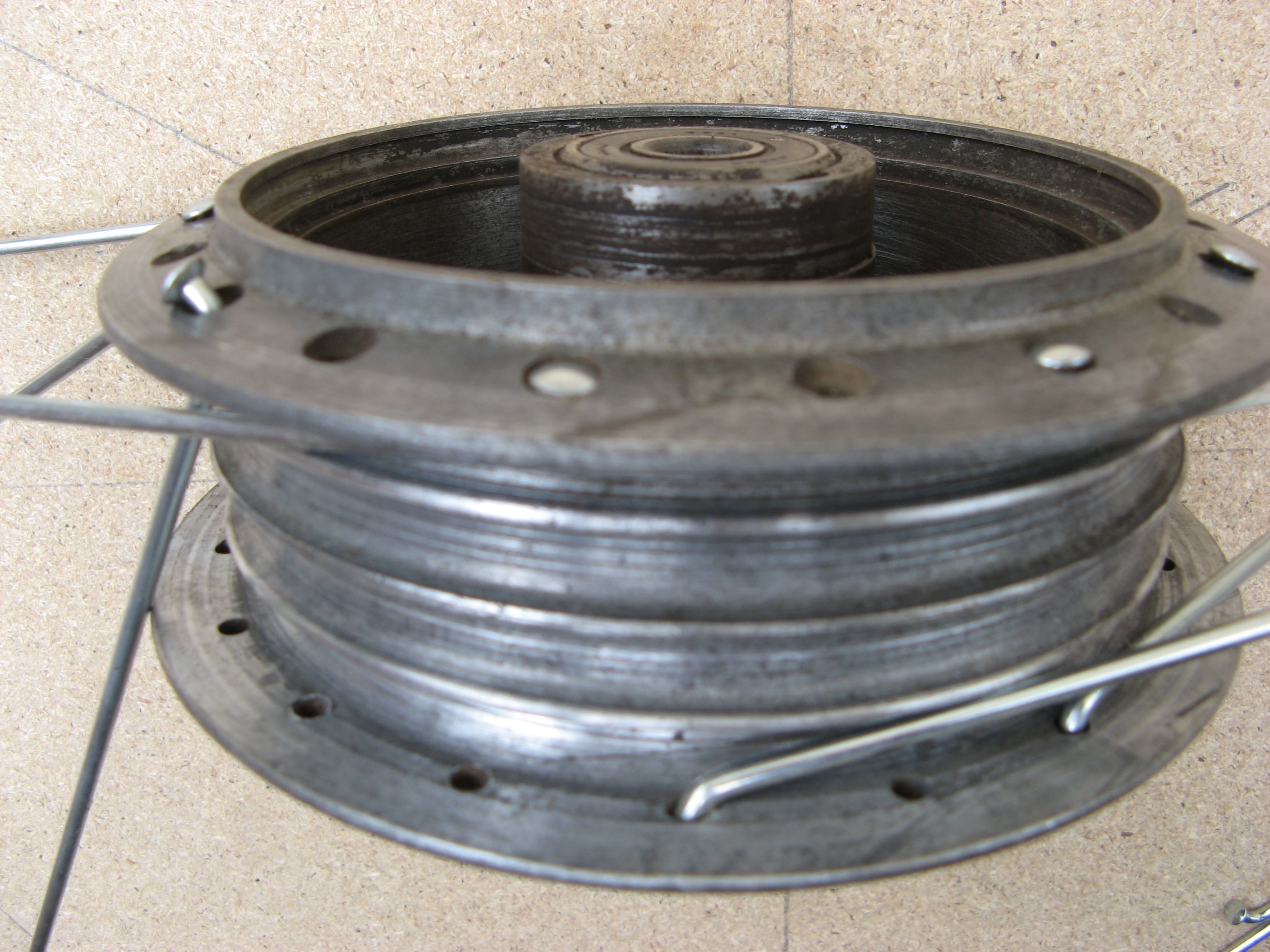
To re-assemble the wheels, a simple jig was made to get the off-set of the rim and hub correct
The jig was a piece of flat board with a hole bored in the centre to take the axle (12mm). Then 3 holes were drilled just outside the rim to take some 12mm threaded rod. These 3 holes were actually drilled 16mm in diameter, to allow some adjustment of the rod position.
Each rod was held in place with a large washer and nut on both sides of the board. The rod was allowed to protrude through the underside of the board to give 3 feet for the jig to stand on and create clearance for the centre axle.
A third nut was then adjusted on each rod to just touch the underside of the rim, on the fully assembled wheel.
The jig was now ready to use. The hub was located by the hole in the centre, and the rim position and height was given by the rods and lock-nuts.
The wheels were dismantled by loosening the spoke nipples with a spanner and then undoing then with an electric screw driver.
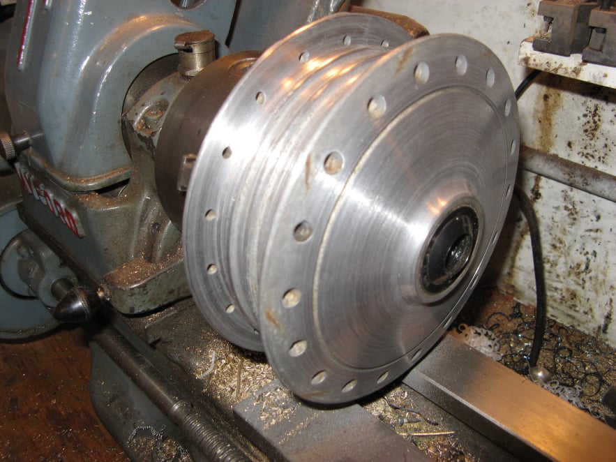
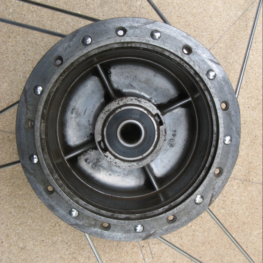
The hubs were spun on the lathe and cleaned using abrasives. The roundness of the brake bearing surfaces was also checked in this setting and they were found to be OK.
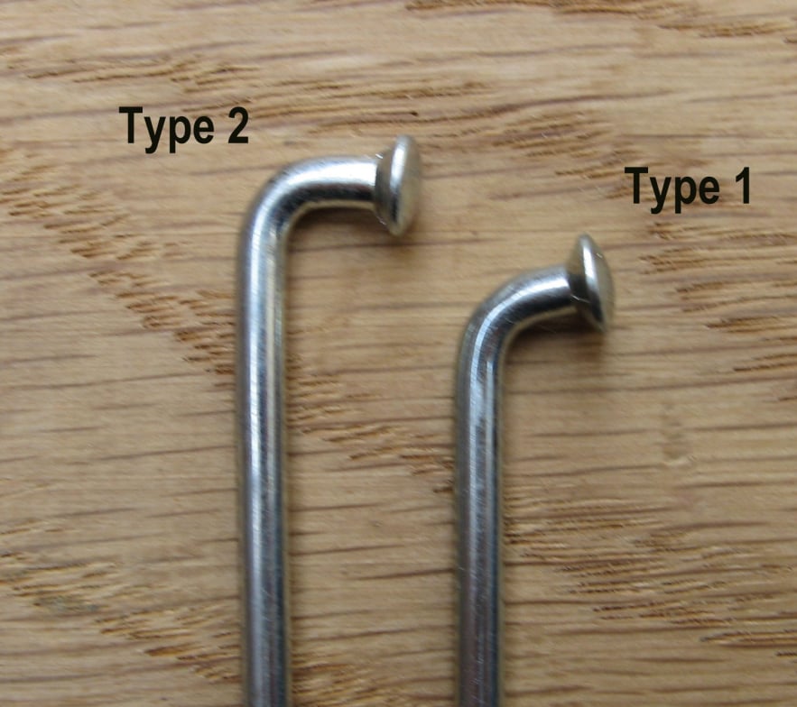
To lace the wheels, the spokes on the inside of the hub were fitted first. These were of the type 1 as shown in the picture above.
The first spokes were fitted on one side in alternate holes as shown above.
The inside spokes were also fitted on the other side of the hub. These were also located in alternate holes, however the holes were off-set from the first side as shown.
With the hub (open side up) and rim placed on the jig, spoke from the top flange was threaded through the hole to the right of the valve hole This would be the datum spoke.
Moving clockwise, all the spokes on the first side were threaded in each 4th hole.
A nipple was fitted loosely to each spoke.
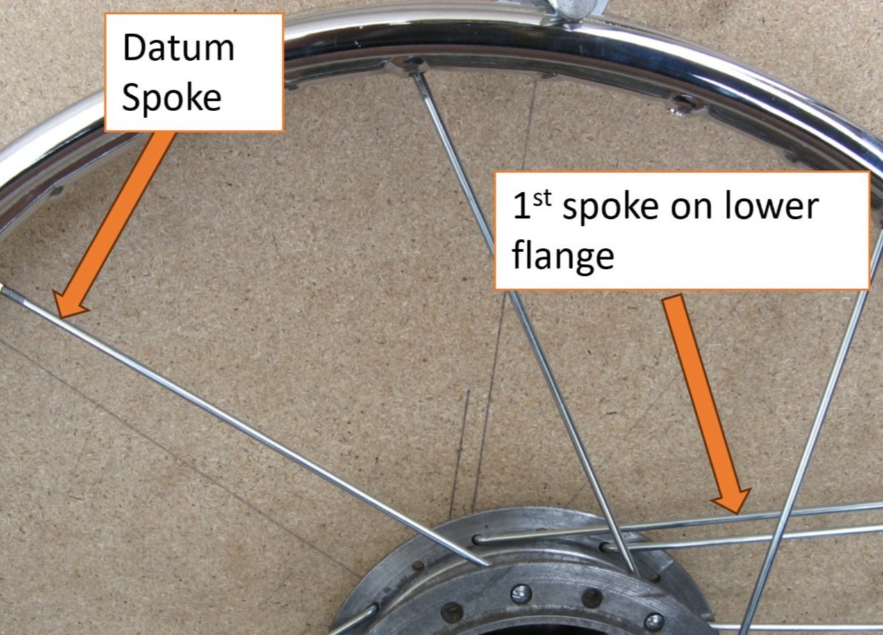
Next the spokes on the lower flange were threaded.
The first spoke on the second side of the hub was the one to the left of the datum spoke. This was then threaded through the 11th hole to the right.
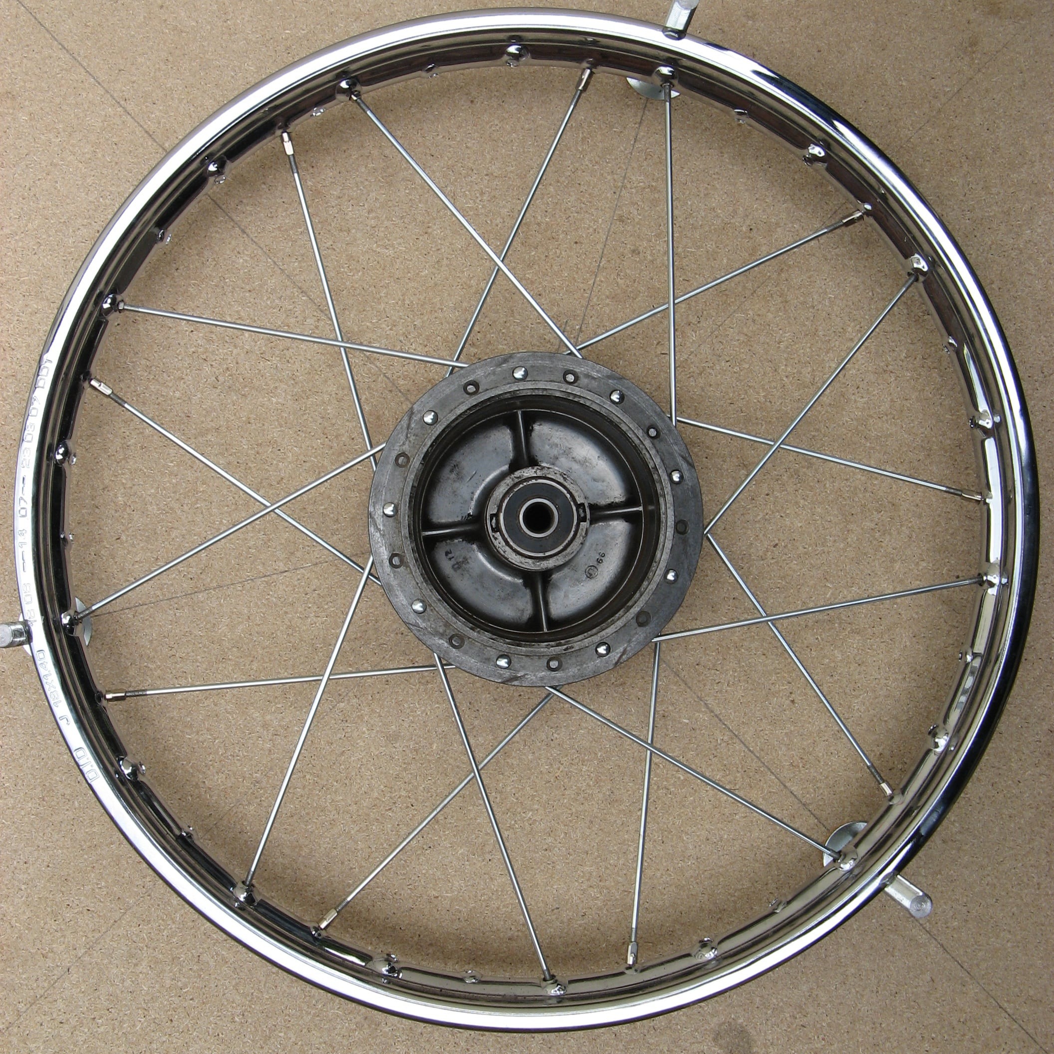
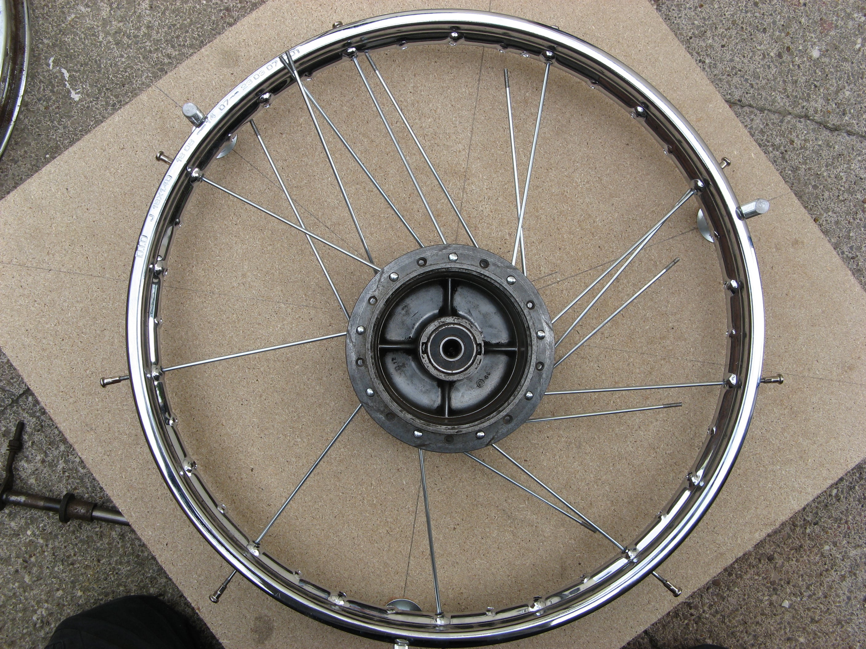
As before the spokes on the second side were threaded through every 4th hole. With all the inside spokes threaded the wheel should be symmetrical and look like this.
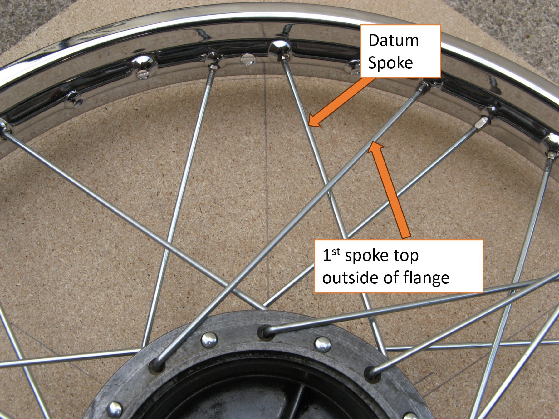
Next the outside flange spokes were threaded on the top side. These were of the type 2 spoke.
The first spoke fitted was 5 holes to the left of the datum spoke on the hub and 3 to the right of the valve hole.
Subsequent spokes were all threaded clockwise in every 4th hole.
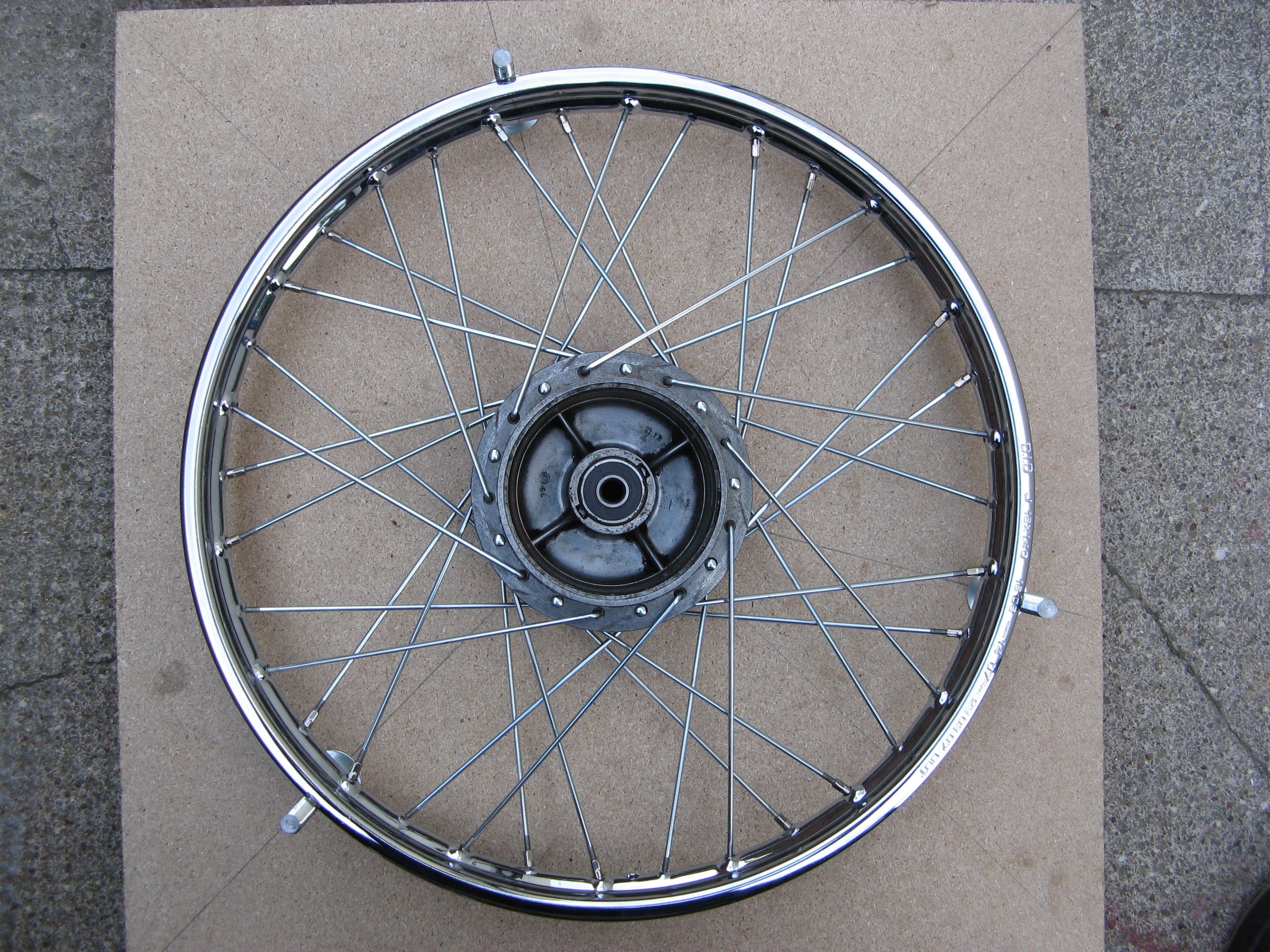
To finish the lacing. The outside spoke on the lower side were threaded through the remaining holes in the hub and rim to give the final layout shown here.
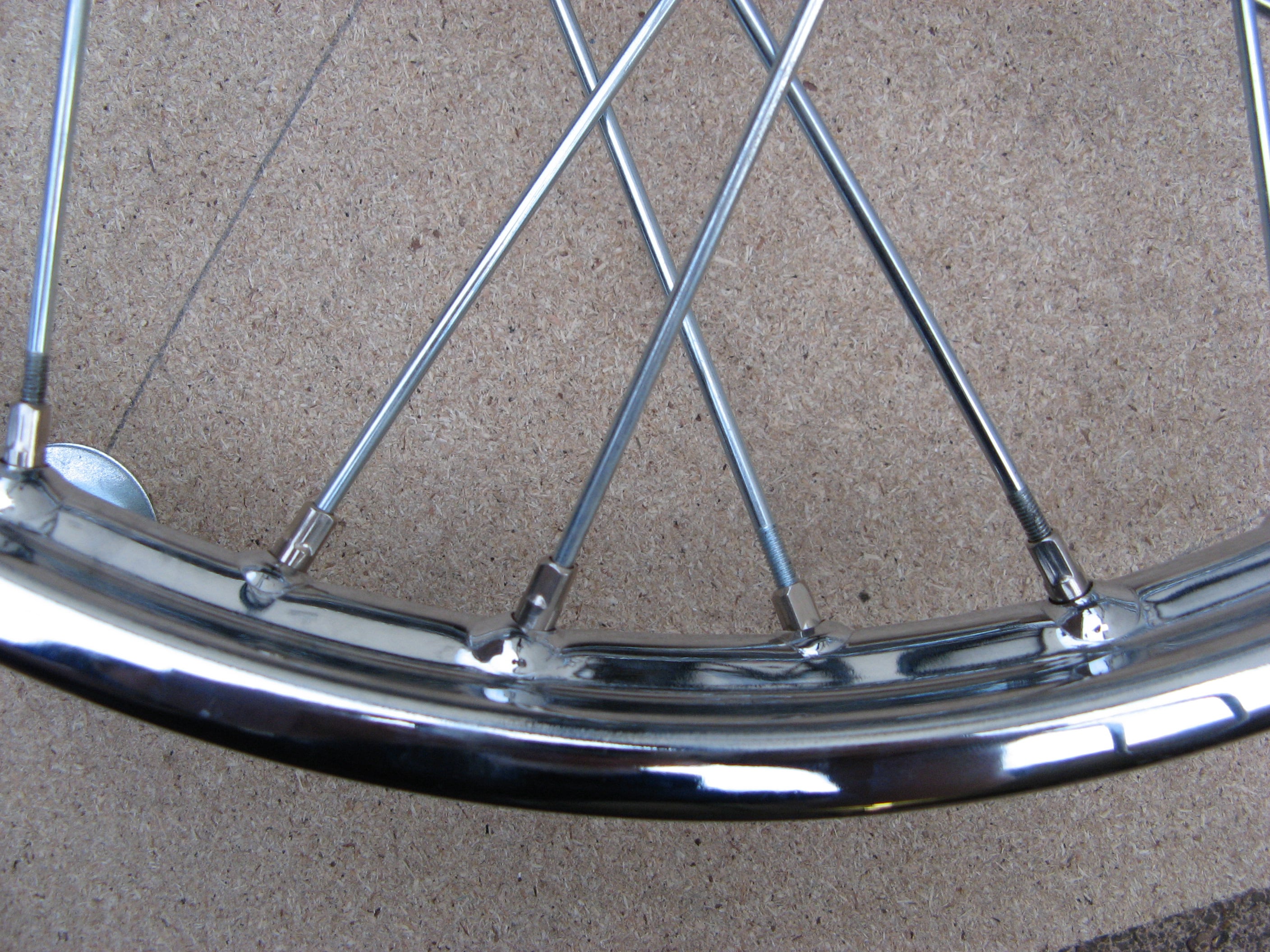
With the wheel in the centring jig the spokes were progressively tightened.
If the situation shown here occurs with the leading spokes showing less thread than the trailing ones (or visa versa) it is because the hub needs twisting within the rim. This can be corrected by slackening the tighter spokes and tightening the looser ones.
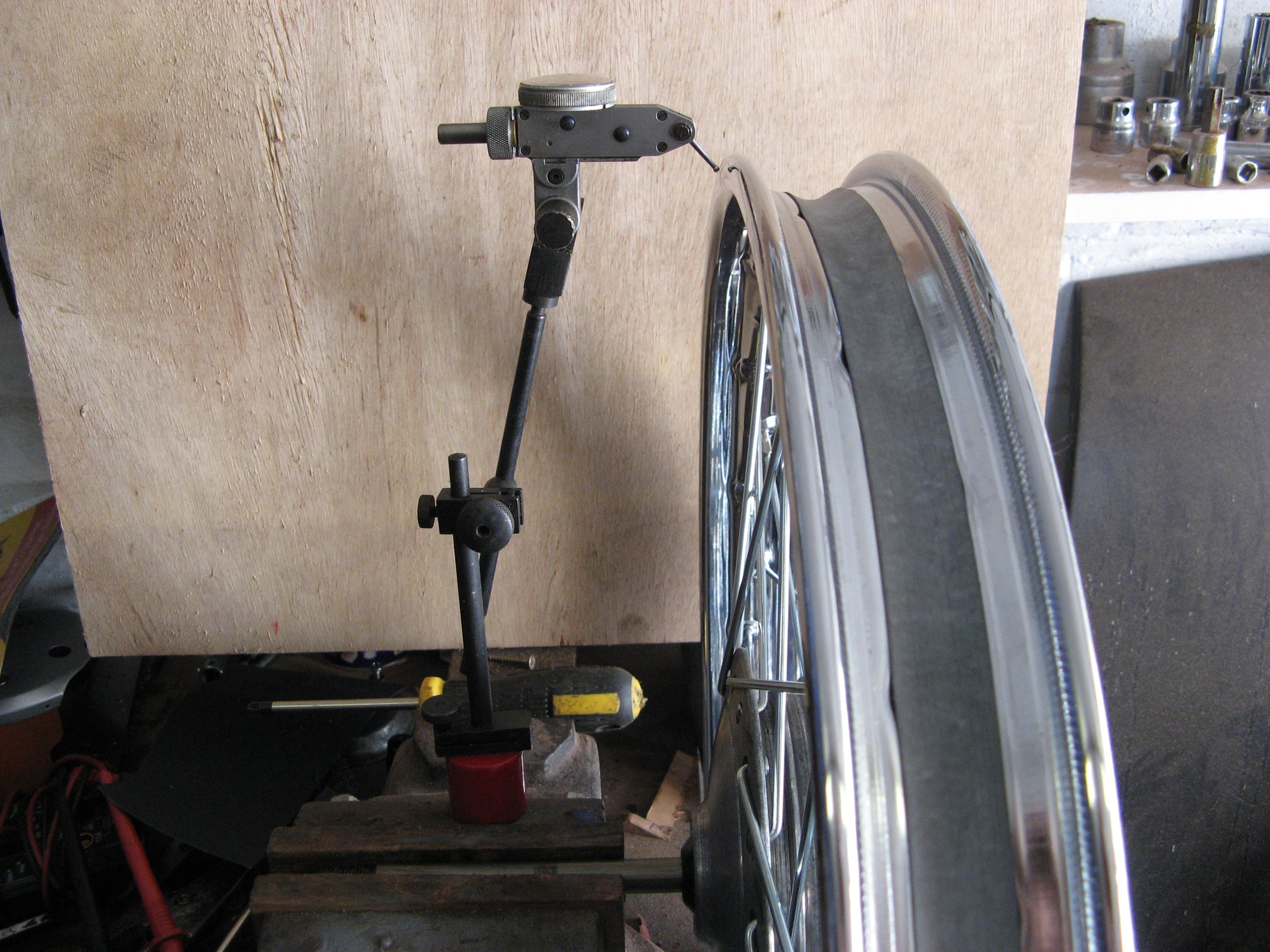
After all the spokes had been tightened so that there was no slack in any of them, the wheel was removed from the jig and placed on a spindle in the vice.
A DTI was used against the rim to measure radial and axial run-out. Each was checked in turn, and the spokes were tightened or loosened to correct things until the wheel was running true.
Once the wheel was running true, the spokes were tapped with the spanner to check for a similar note between them, highlighting any which might need tightening.
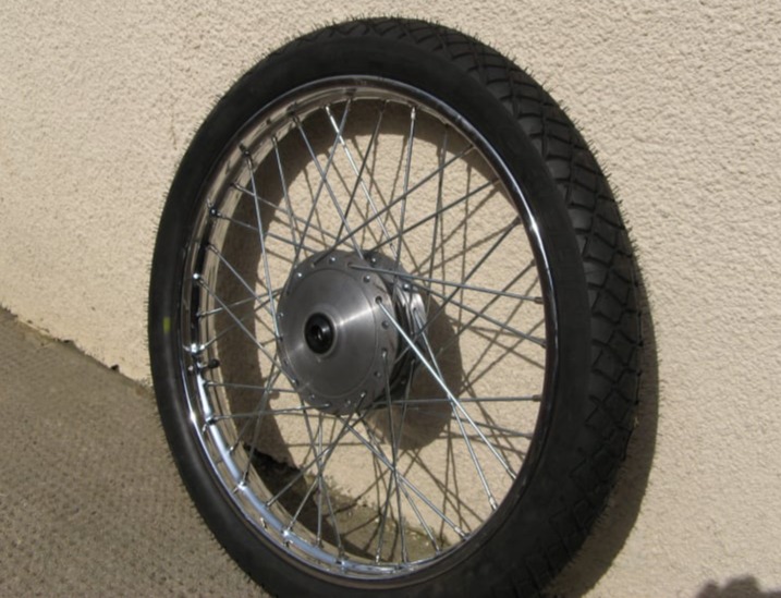
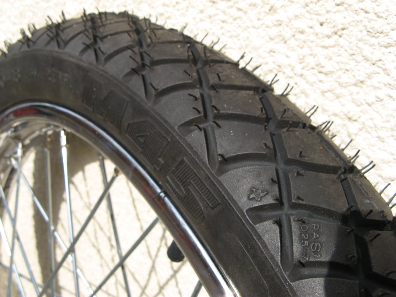
To finish the wheels were equip with Michelin M45 Road Tyres.

AI Website Generator