Mobirise Website Builder

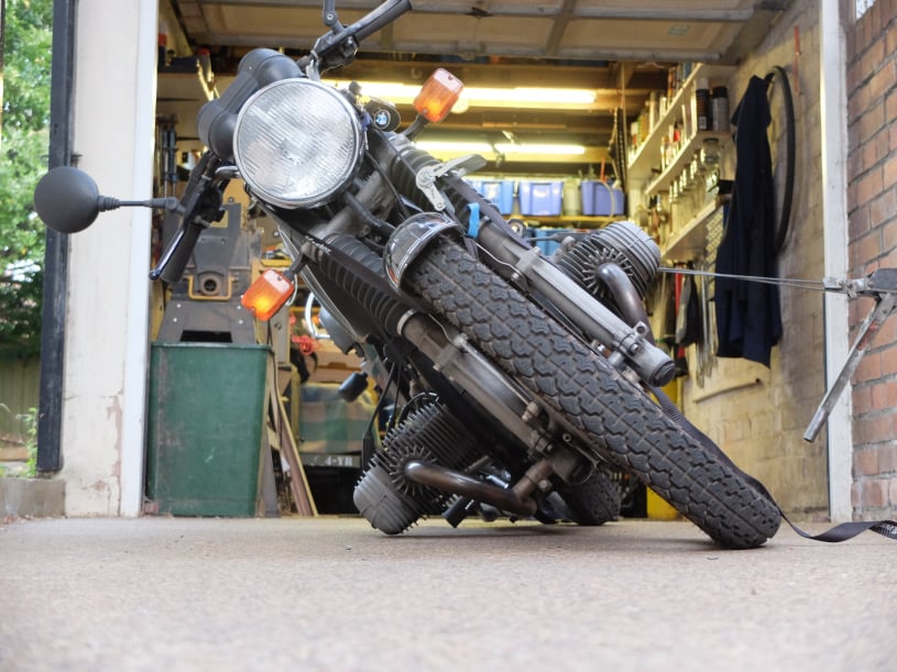
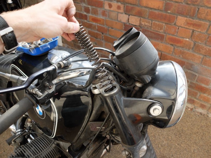
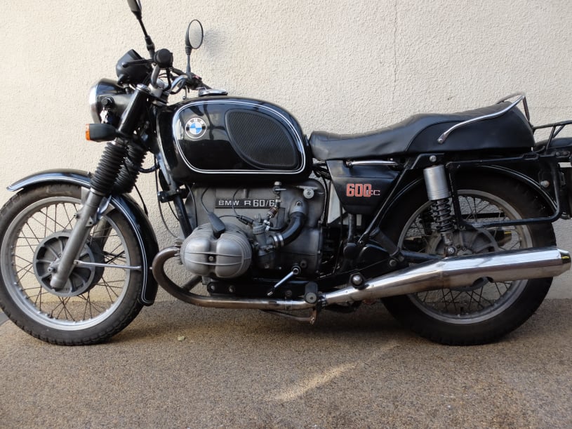
Lowering the BMW R60/6

Motorcycle suspension is critical to the safe handling of a bike and so adjustments should not be made lightly.
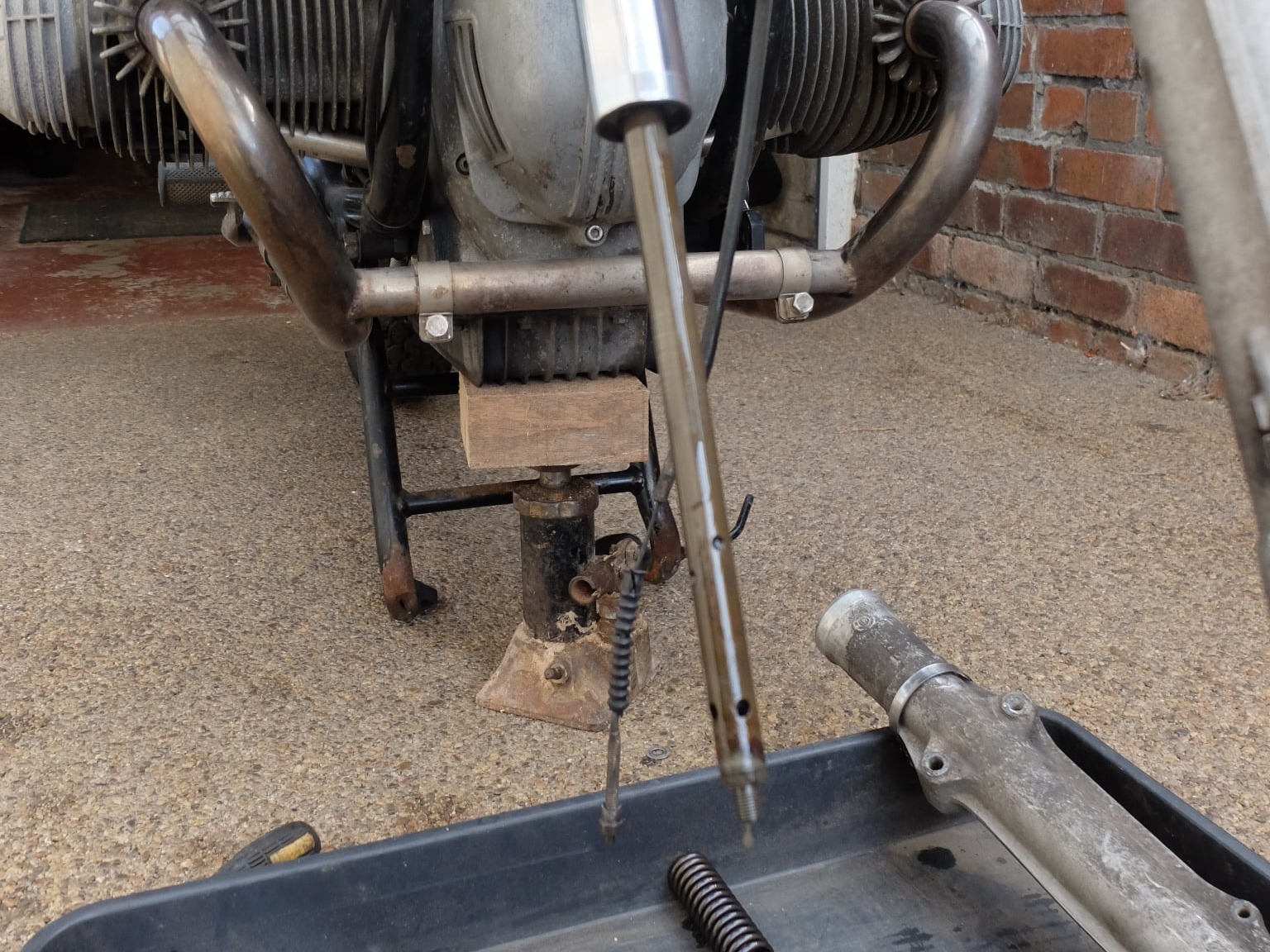
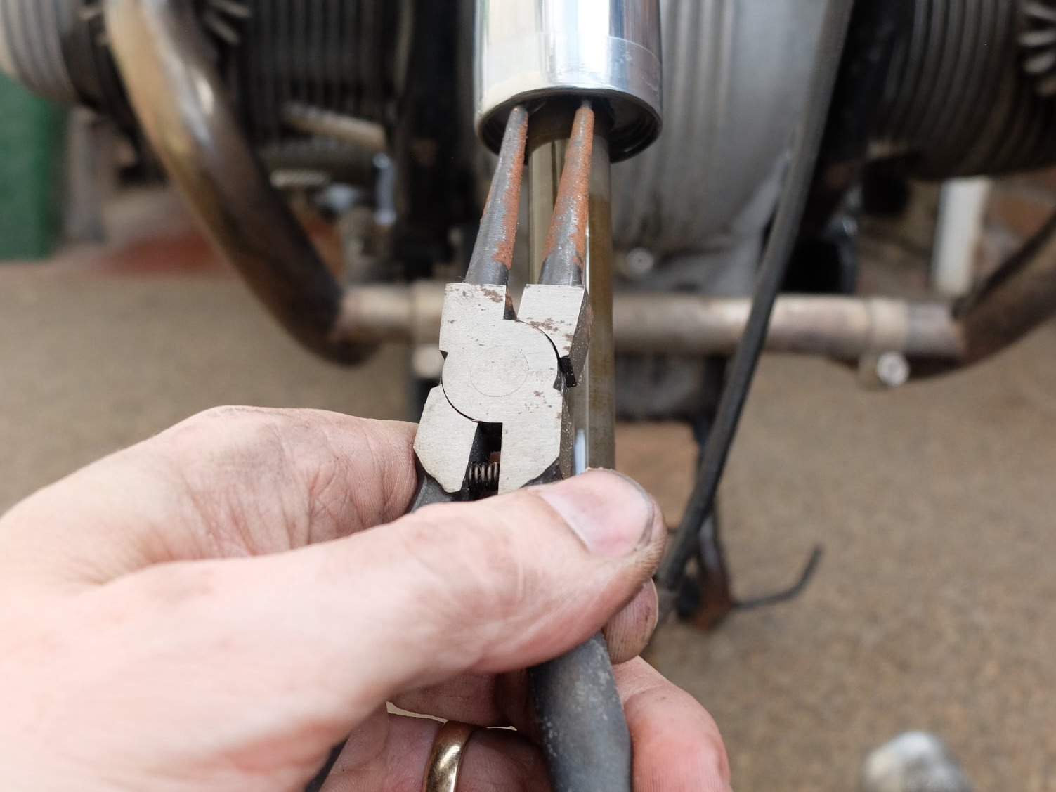
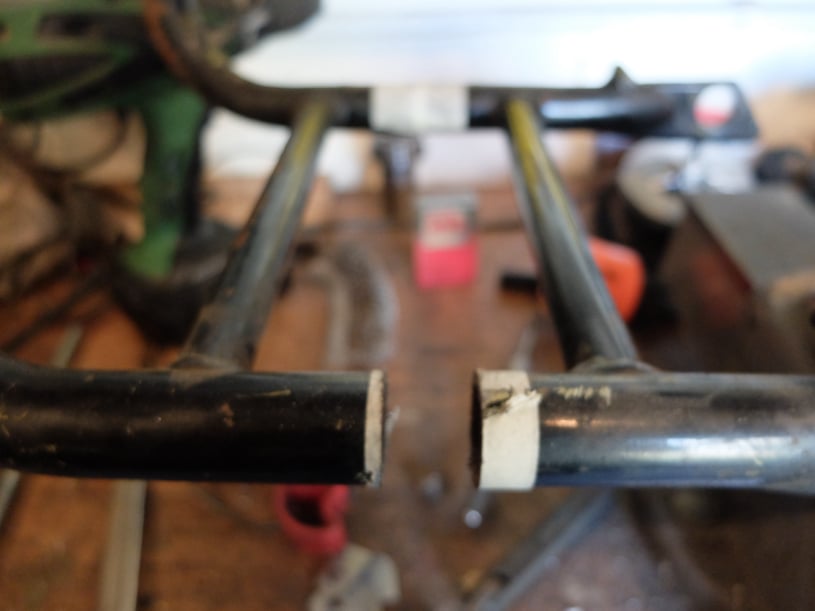
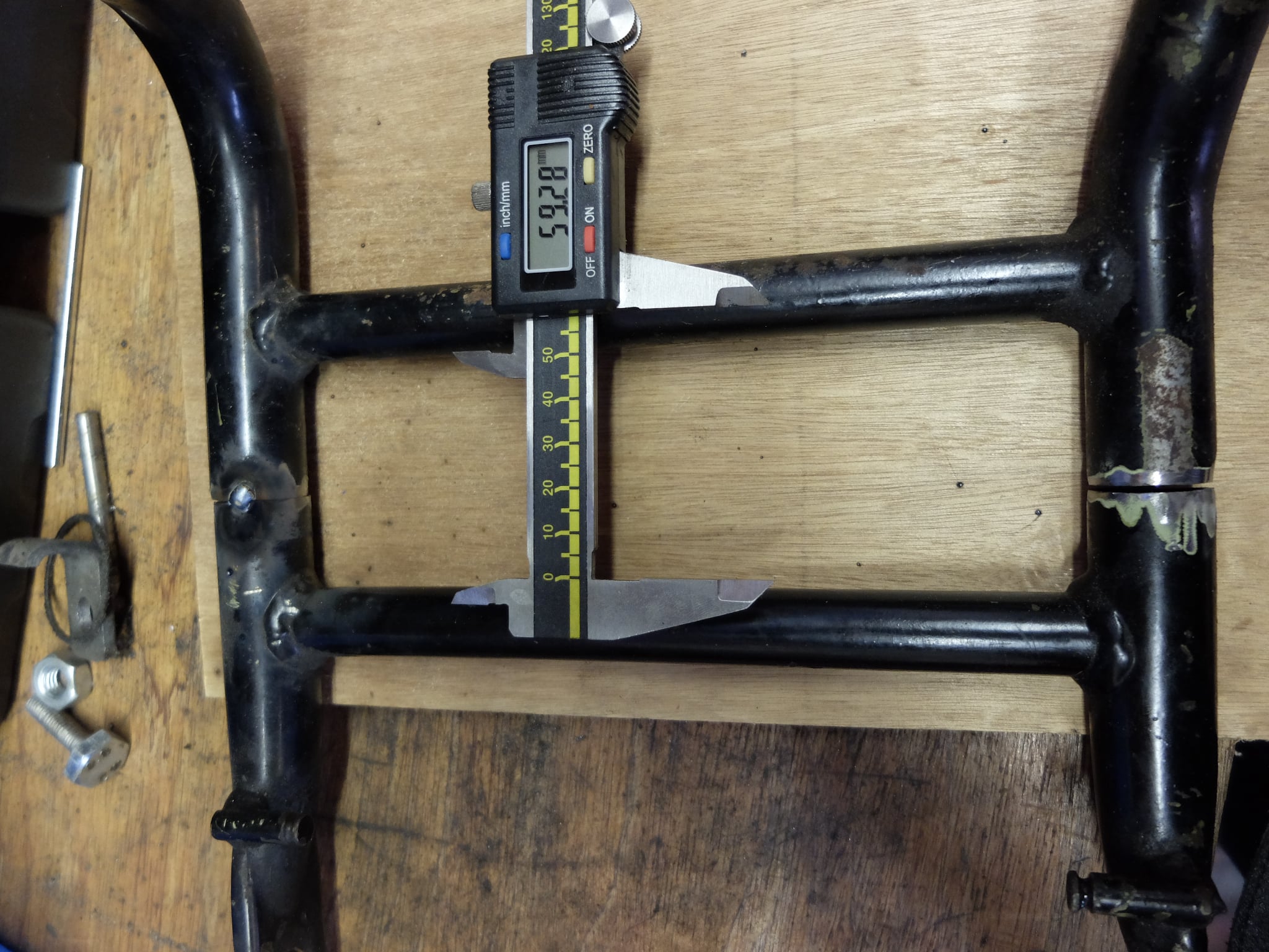
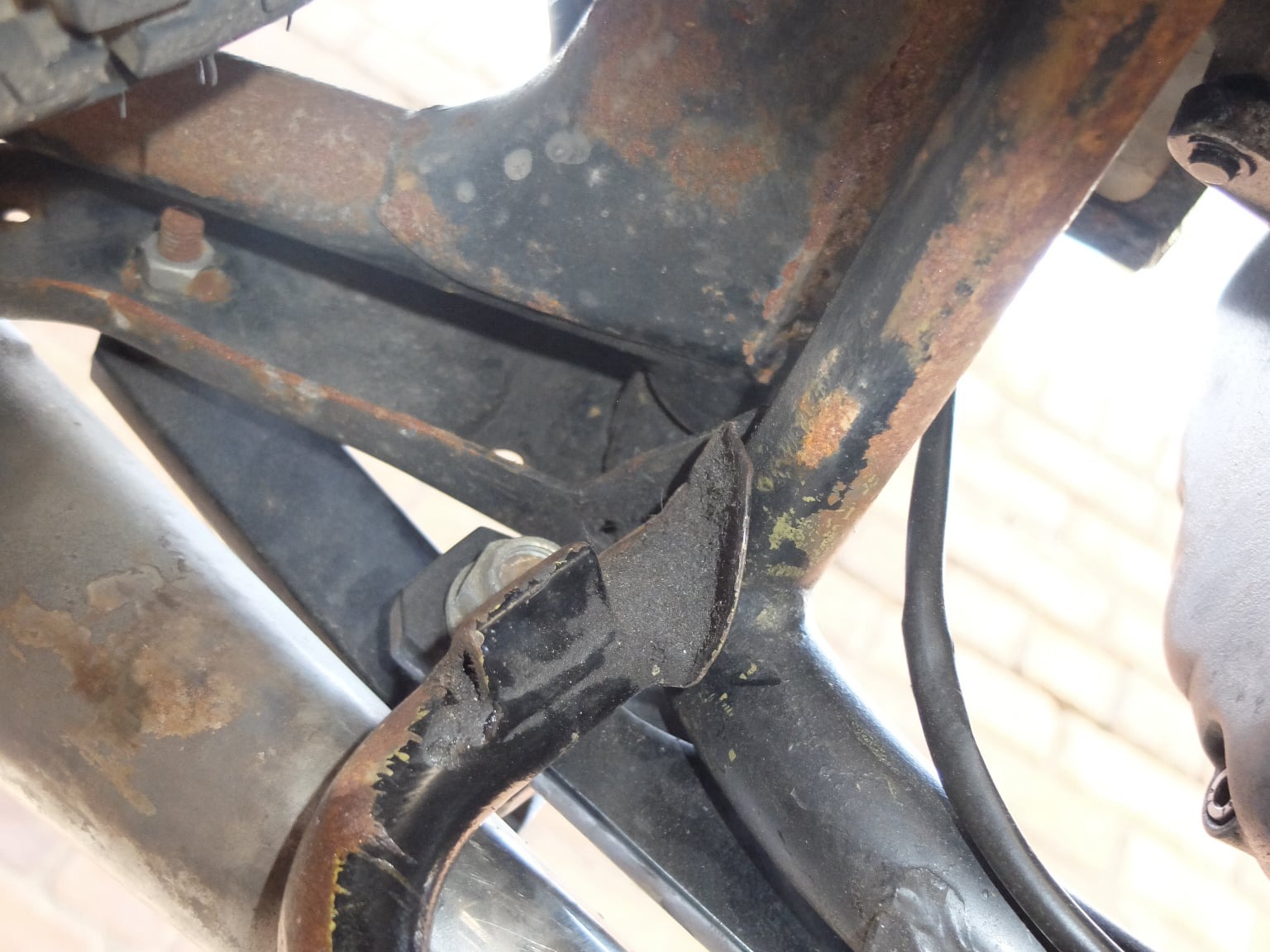
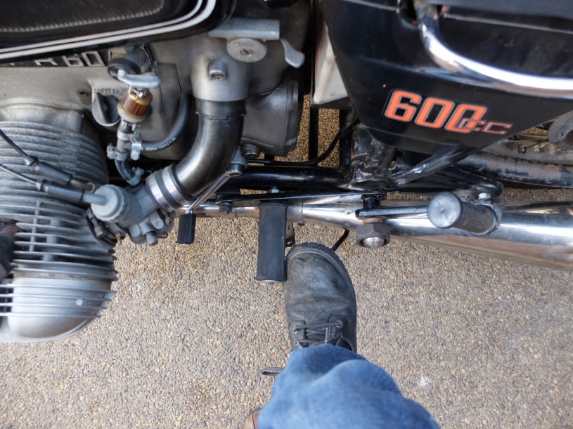
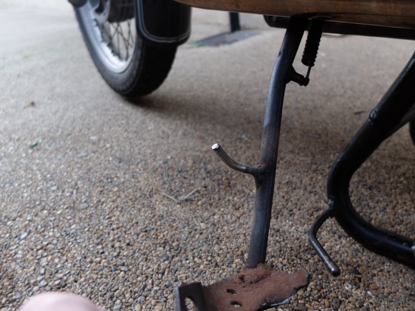
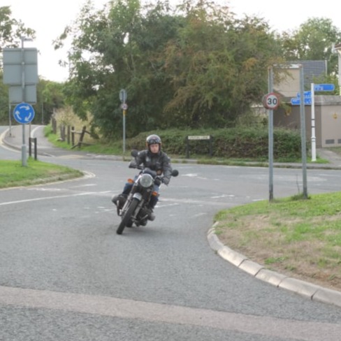
This page details how this BMW R60/6 was lowered to make it easier to ride for a short rider, but these changes should only be made if you are confident and must be made at your own risk.
In this case the result was satisfactory and preferable to an over-tall bike which also had safety implications.

Lowering suspension can change a bike's steering geometry and also affect ground clearance and so each of these issues was investigated before making any changes to the bike.

Some facts to consider.
Shorter wheel base bikes handle more quickly and the SWB /5 BMW's from the 1970's were sometimes criticised for this. The R60 wheelbase was 1465mm and the SWB /5 bikes were 1385mm. So any changes should avoid getting near the SWB wheelbase.

Trail of the bike should be maintained to factory specification. Trail gives the bike a self-centring action when cornering. Too much trail can make steering heavy and too little trail can give twitchy handling possibly leading to steering oscillations. Touring riders who overload the back of a motorcycle can lower the back to an extent that trail is reduced because of the tilt of the bike and there have been examples of handling problems because of it.

A lower bike can be expected to have less corning clearance particularly the BMW flat twins with their cylinders sticking our either side. Even standard bikes sometimes have scrape markings on the rocker covers so a reduction in corning clearance should be minimised although can be somewhat expected.

Another change to be expected was a change to the drive shaft angle.

Finally both the centre stand and side stand would have to be checked for compatibility with the lowered bike. This would mean checking the stand operations both deployed and folded away.

Mobirise Website Builder

To check cornering clearance the R60 was anchored to a wall and lowered to a point the rocker cover just touched the ground. At this point the angle was checked.

Then the suspension was compressed with ratchet ties to make it 20mm shorter front and back and the same measurement was made.

The result was a decrease in lean angle (from the vertical) of 47.2° to 45.2°

Some calculations were made on a proposed change of 20mm lowered suspension.

Consequences of lowering just the back.
This should be avoided as it would decrease trail at the front, but for a worse case scenario how much would the trail decrease?
Calculations showed than lowering the back 20mm would relax the headstock angle by 1.2° with a consequential decrease in trail of 5 or 6mm. Standard trail on the R60 was 89mm; so 6mm would be a 7% reduction in trail.

Lowering the back would also change the angle of the drive shaft. The angle change was found to be 3.4° but this would actually be a decrease in angle rather than increase (ie the joint would be straighter) which should not cause any strain on the universal joint.

Lowering the front by 20mm would reduce the wheelbase by 9mm. However lowering the back would actually increase the wheel base by 3.7mm so the net decrease would be 5.3mm. This is 0.35% of the standard wheelbase. The new wheelbase would be 1459mm which would still be much longer than the SWB BMW's with suspect handling.

Mobirise Website Builder

The amount of suspension lowering was based on the rear shocks which were replaced with a pair from a later R65 BMW.
These would have the correct spring rate for the R60 and were found to be 20mm shorter than the original.

These parts were a simple bolt-on replacement.

The R65 shocks were rebuilt with the shroud from the old parts to keep appearances similar to standard.

With the rear of the bike lowered the same amount of lowering was needed at the front to keep the bike's trail the same.

Two changes were made on the forks to achieve this change. First 20mm was cut from the top of both fork springs. Second a 20mm spacer was added to the bottom of the damping rod to limit fork travel.
The process used was to leave the top of the fork secured in the bike triple tree to try and maintain alignment; modification work was done from the bottom.

Mobirise Website Builder

The fork springs can be removed by first removing the handlebars and then unscrewing the top fork cap with a pin spanner.

Mobirise Website Builder

The spring retaining nuts on the fork leg top are known to be tight. A 32mm socket was machined on the lathe to have no chamfer on the inner faces to reduce the chance of it slipping.

Mobirise Website Builder

A long bar will be needed to undo the nut while the bike is held steady on the centre stand. The the springs can then be extracted.

Mobirise Website Builder

At the bottom of the forks, the wheel and mudguard should be removed.

Mobirise Website Builder

The 13mm nut at the bottom of the fork can be removed by first peeling off the dust cap and then turning a 13mm socket whilst holding the central hex screw stationary.
Without holding the central screw the whole damper road can turn.

Mobirise Website Builder

The lower fork caps can be removed with a suitable socket and with the axle in place to stop the lower part of the fork rotating.

Mobirise Website Builder

To remove the lower fork leg the rubber boot should be unclamped at the bottom and the fork leg slid off the stanchion.
With the lower fork lower part removed the damper rod is exposed.

Removing the damper rod through the bottom of the fork leg should be avoided because the threads on the inside of the fork can damage the damper seal. So care should be taken to hold the damper rod up for the next few steps.

Mobirise Website Builder

To insert a spacer under the damper piston it is necessary to remove a circlip and the "screwed-in" caps.

The circlip can be removed with pliers (mind your eyes)......

Mobirise Website Builder

......and then a flat piece of steel can be ground to size to unscrew the caps via the two internal notches. To allow for this tool to be used it will be necessary to push the damper rod up inside the fork stanchion out of harm's way.

Mobirise Website Builder

After removing both caps and any washers the damper rod should be propped up to stop it dropping out the bottom of the fork leg and possibly damaging the damper piston.

Mobirise Website Builder

The lathe was used to turn two 20mm long spacers with a 15mm clearance hole in the centre and 25mm outside diameter.

Mobirise Website Builder

The spacers should be inserted below the damper piston as shown.

Mobirise Website Builder

With one spacer installed there should be a measurable difference in the lowest position of the damper rod.
Next, the same modification must be done to the other fork leg.

Mobirise Website Builder

Both springs should be marked to have 20mm cut off the top with a grinder.

Mobirise Website Builder

With the suspension modified the centre stand still worked but required a lot more effort to operate. So it was marked to have 20mm cut from between the cross-braces.

Mobirise Website Builder

Setting the halves of the stand parallel for welding

Mobirise Website Builder

When folded up the stand just cleared the bike frame.

Mobirise Website Builder

The side-stand length was reduced by 20mm to ensure the bike leaned as a secure angle but the leg was shorter and therefore didn't reach as far out as before.

Also, when retracted, the foot of the stand was almost directly under the foot peg making it difficult to deploy with biking boots on. It was also made worse by the shorter centre stand because the deployment prong for this was now 20mm nearer the foot peg.

One solution would be an after market side stand most of which have adjustable reach.
However for this situation the prong for the centre stand was modified to move it back a bit to give more clearance for a foot.

Mobirise Website Builder

In the end the side stand was modified with an additional prong to enable easier deployment.

Mobirise Website Builder

Road test and handling

A steady and careful road test was use to prove the handling was predictable and capable.
Cornering clearance was not a problem at responsible speeds (my speeds) and there were no unusual shimmy or oscillations from the steering.

Offline Website Builder