Mobirise Website Builder

BMW R60/6 Gearbox Overhaul

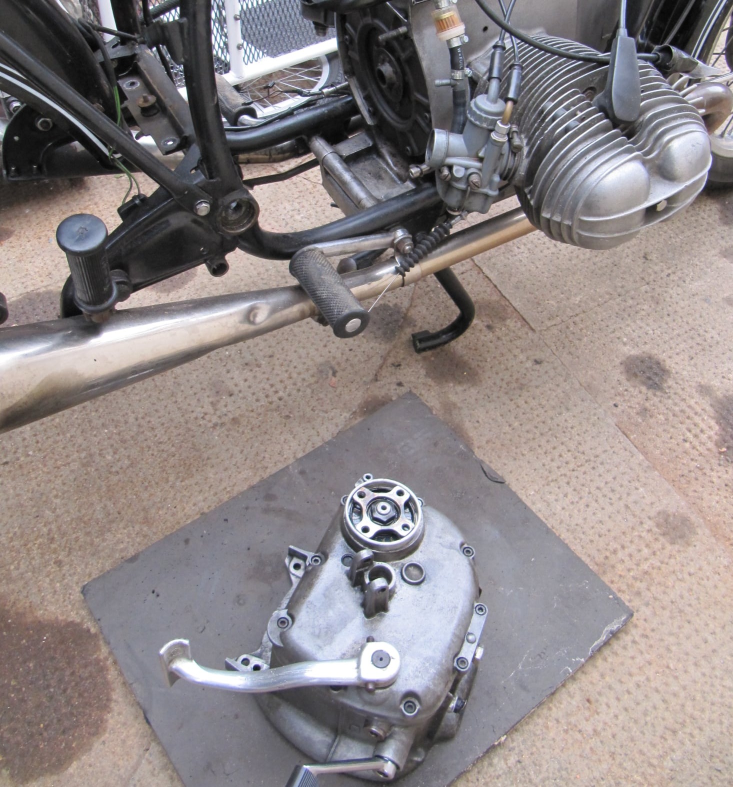
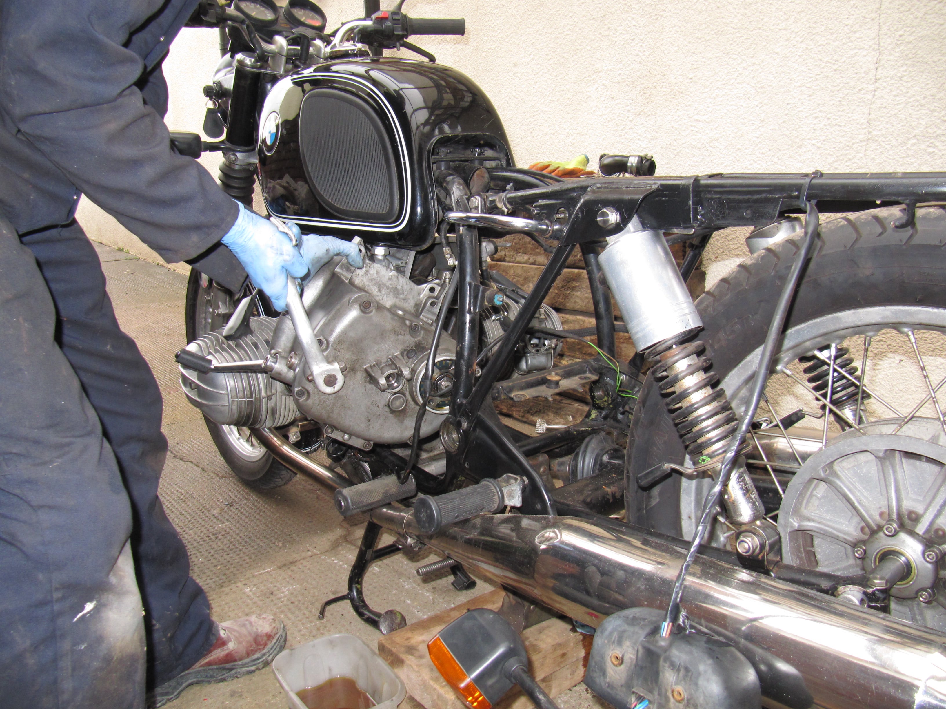
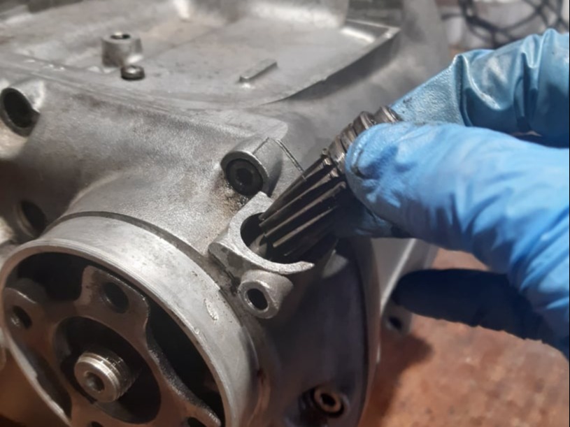
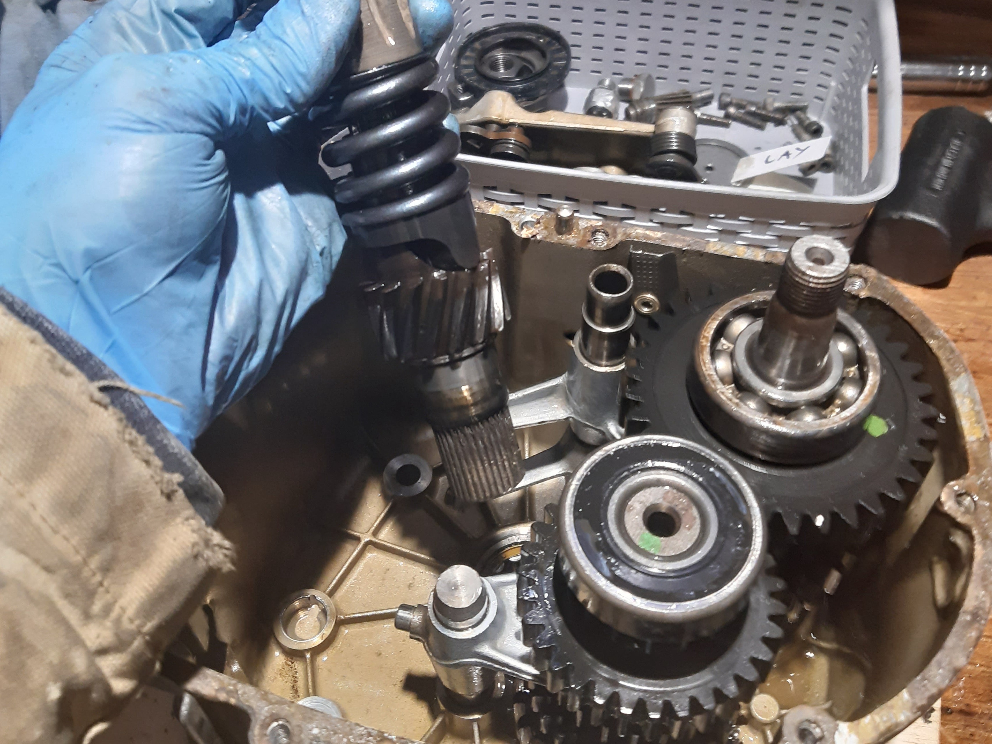
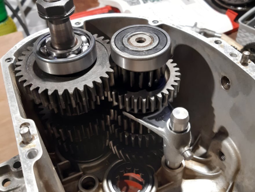
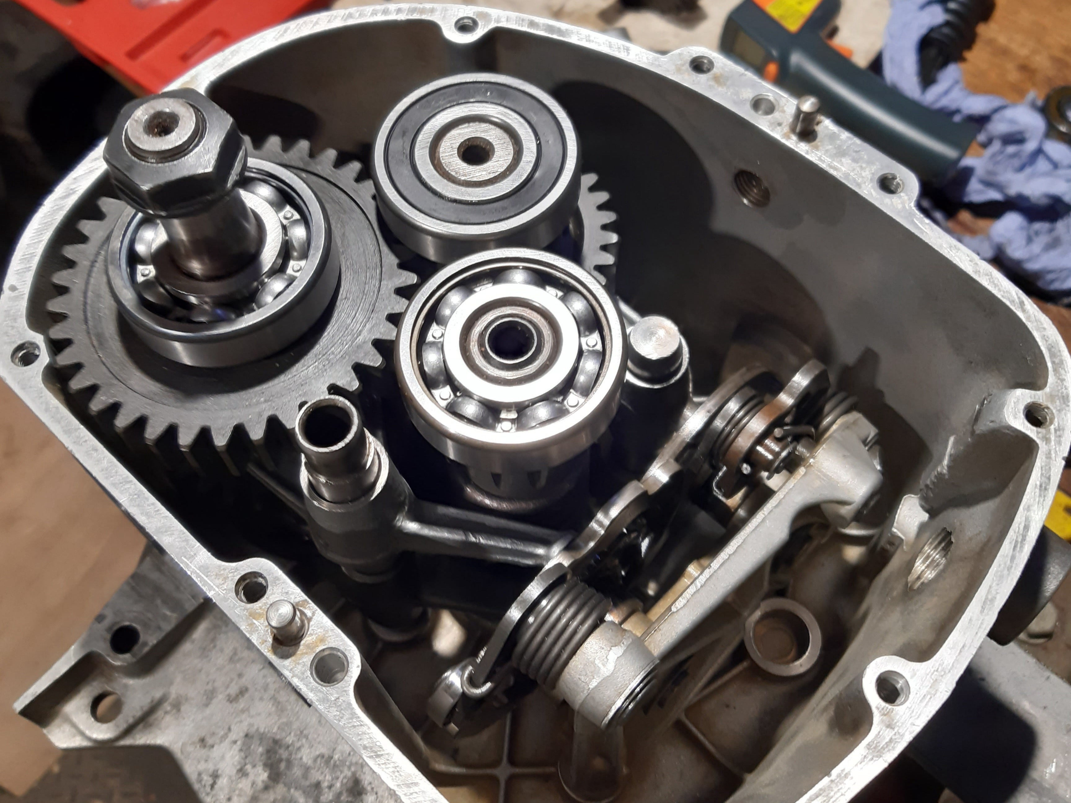
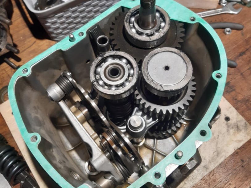
Unlike most other bikes, the BMW boxer gearbox can be removed as a separate unit without the need to remove the engine from the frame, or split the crankcase. The gearbox is a self contained unit with its own oil.

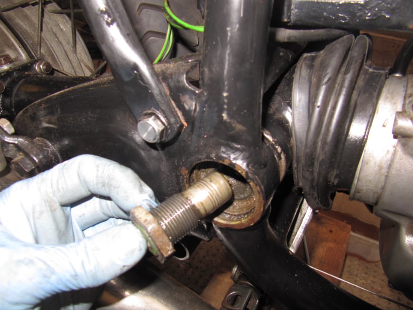
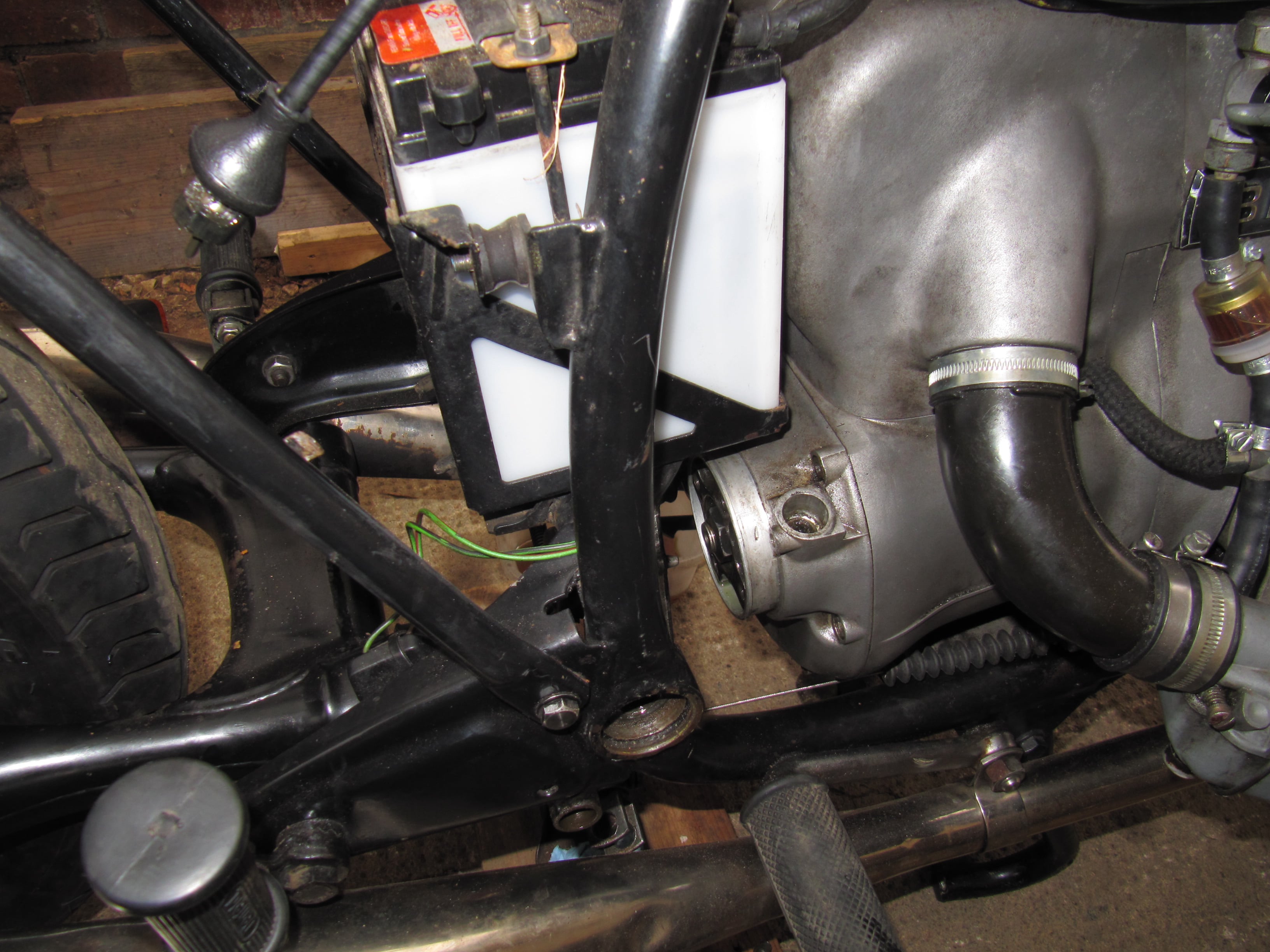
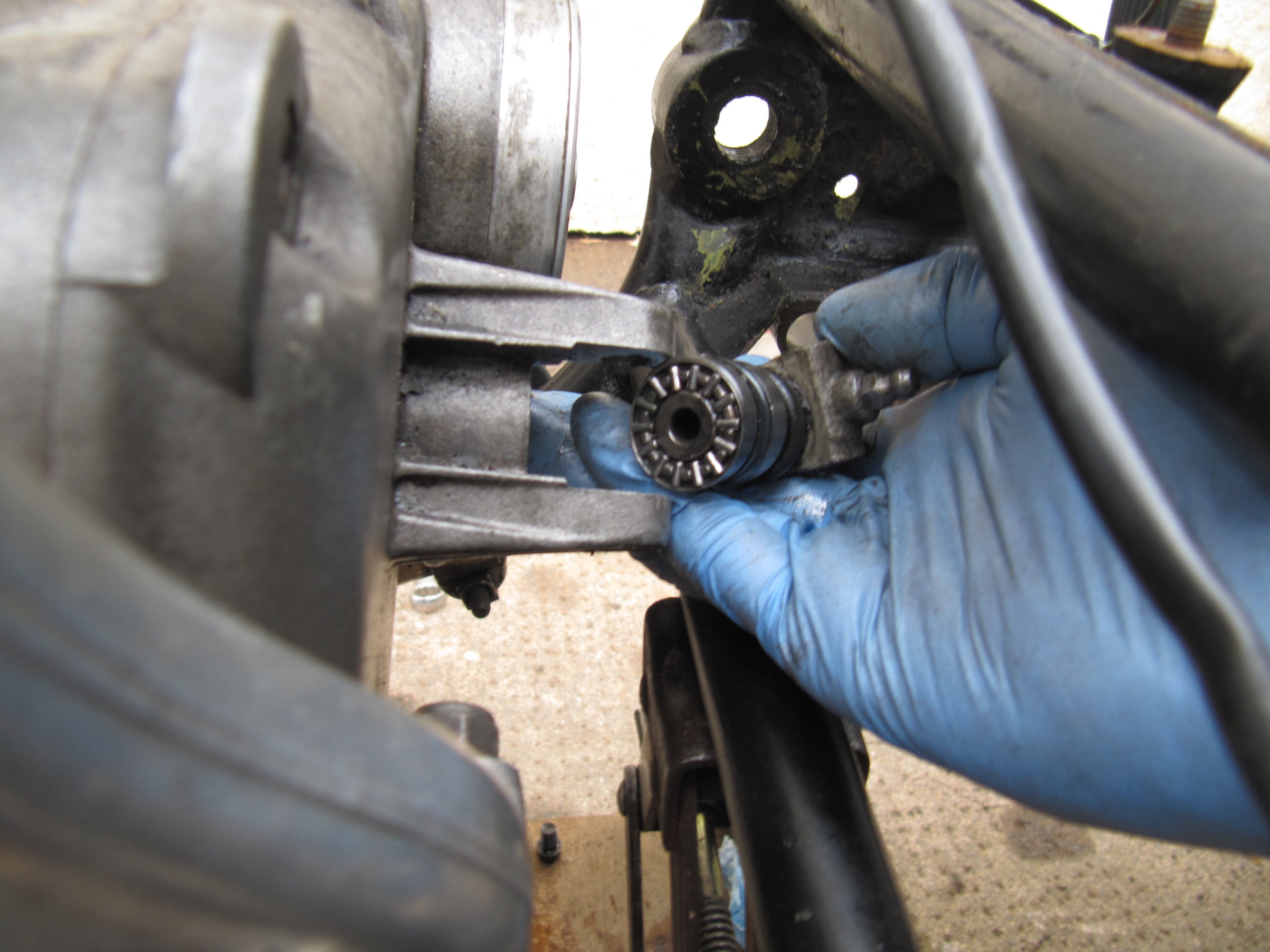
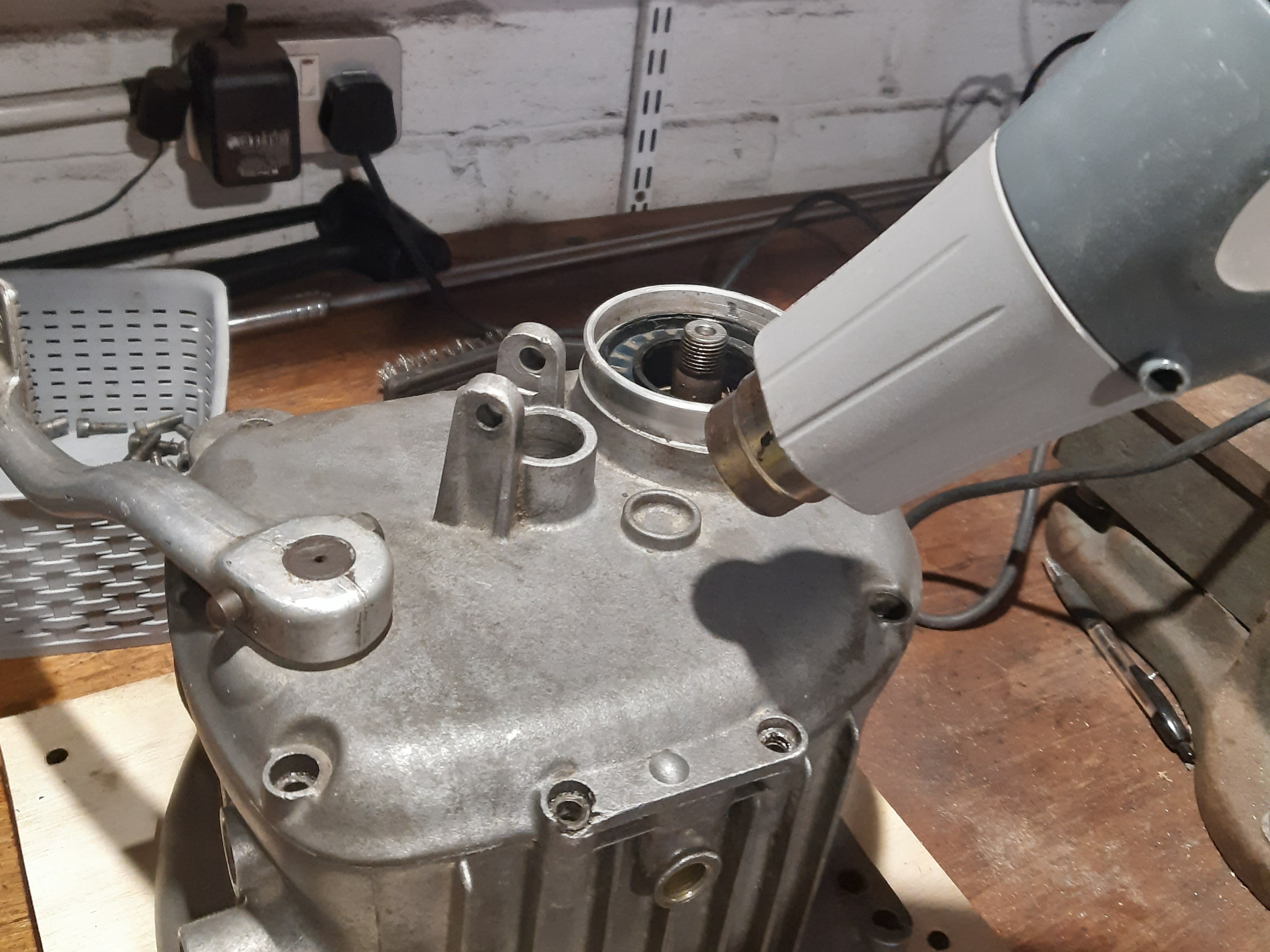
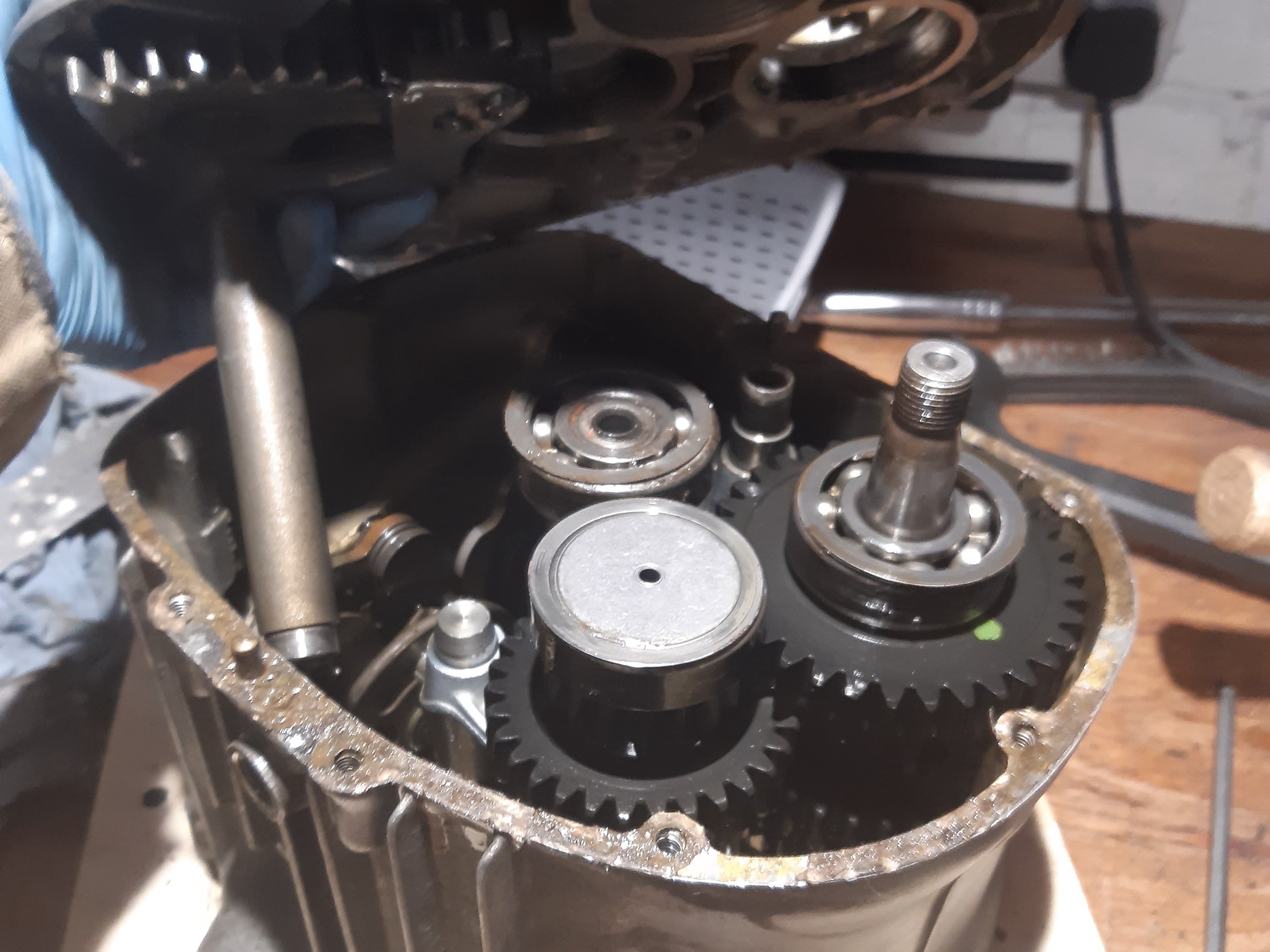
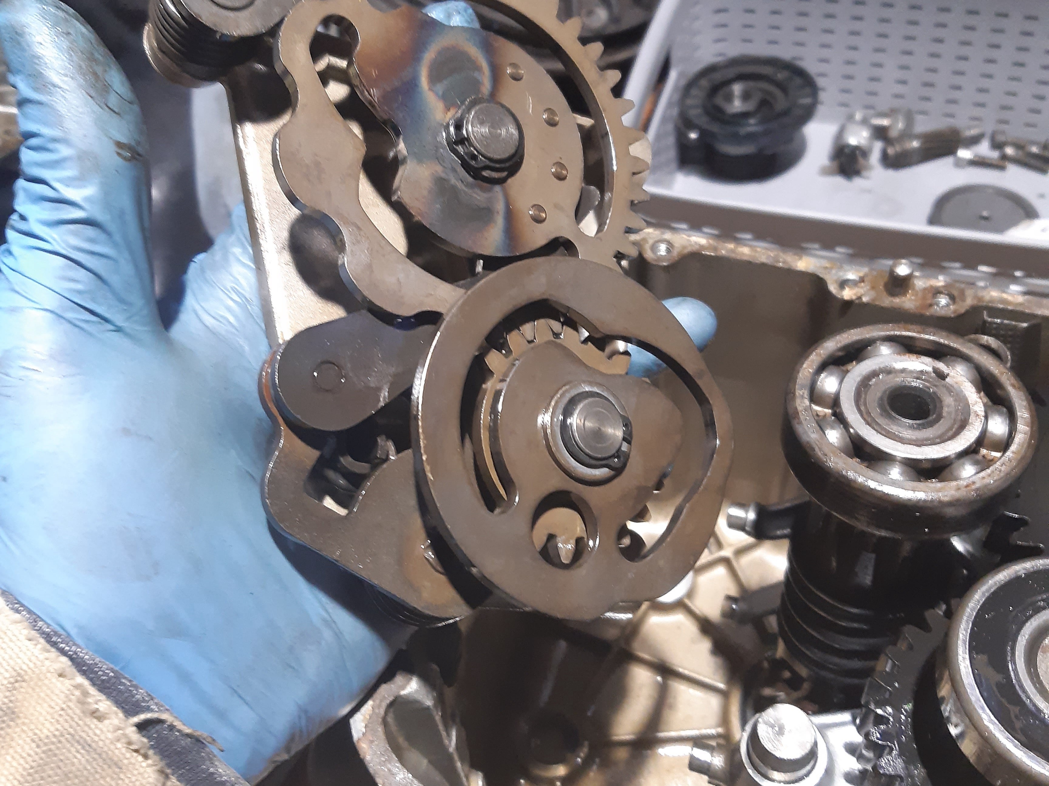
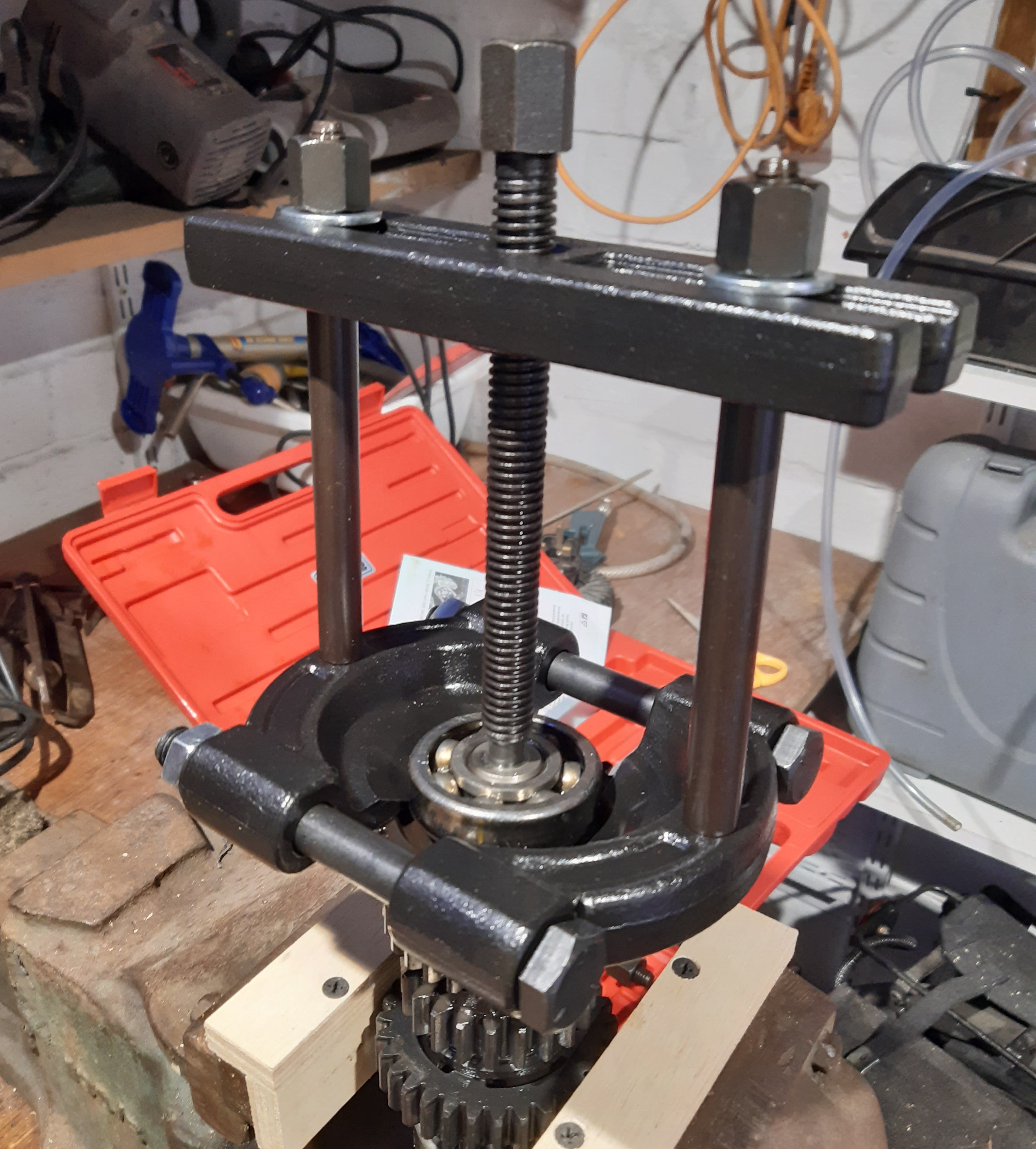
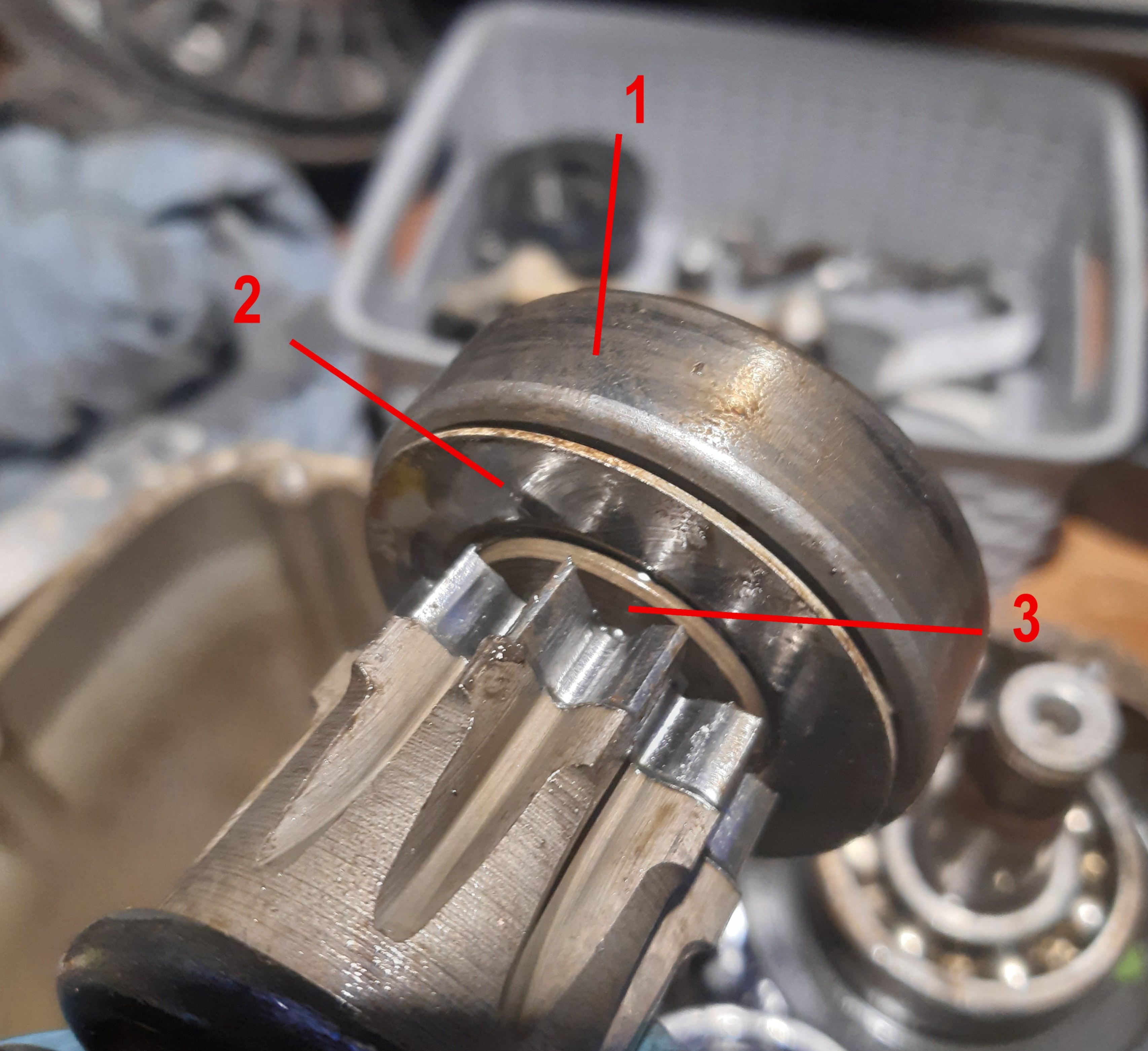
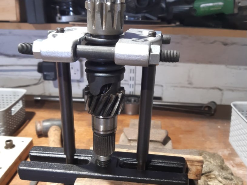
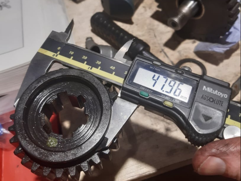
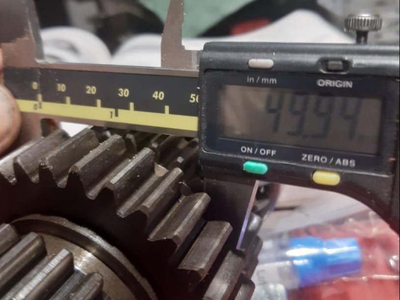
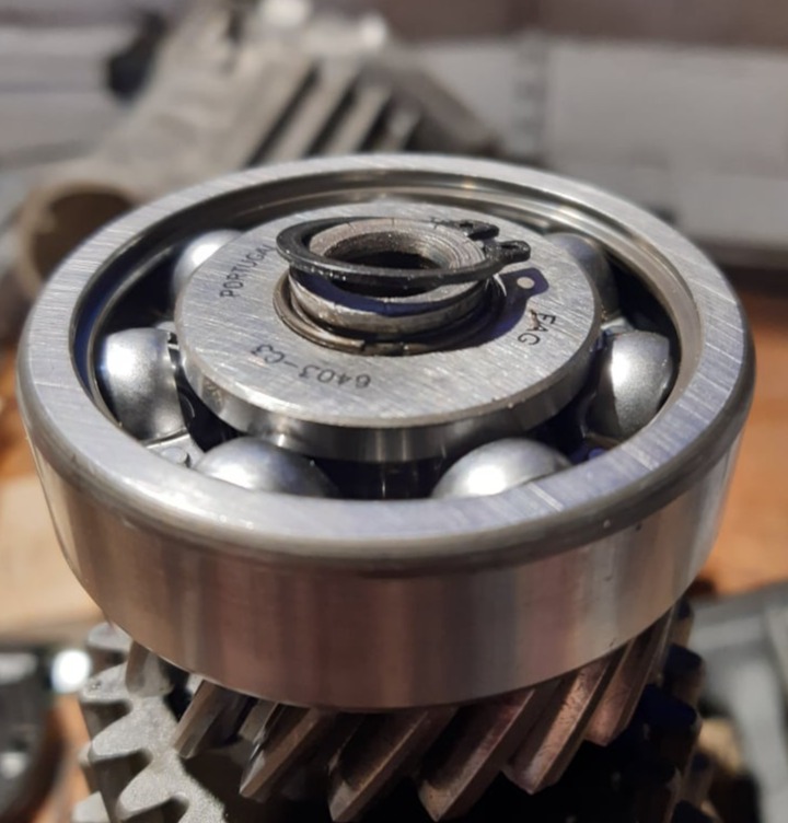
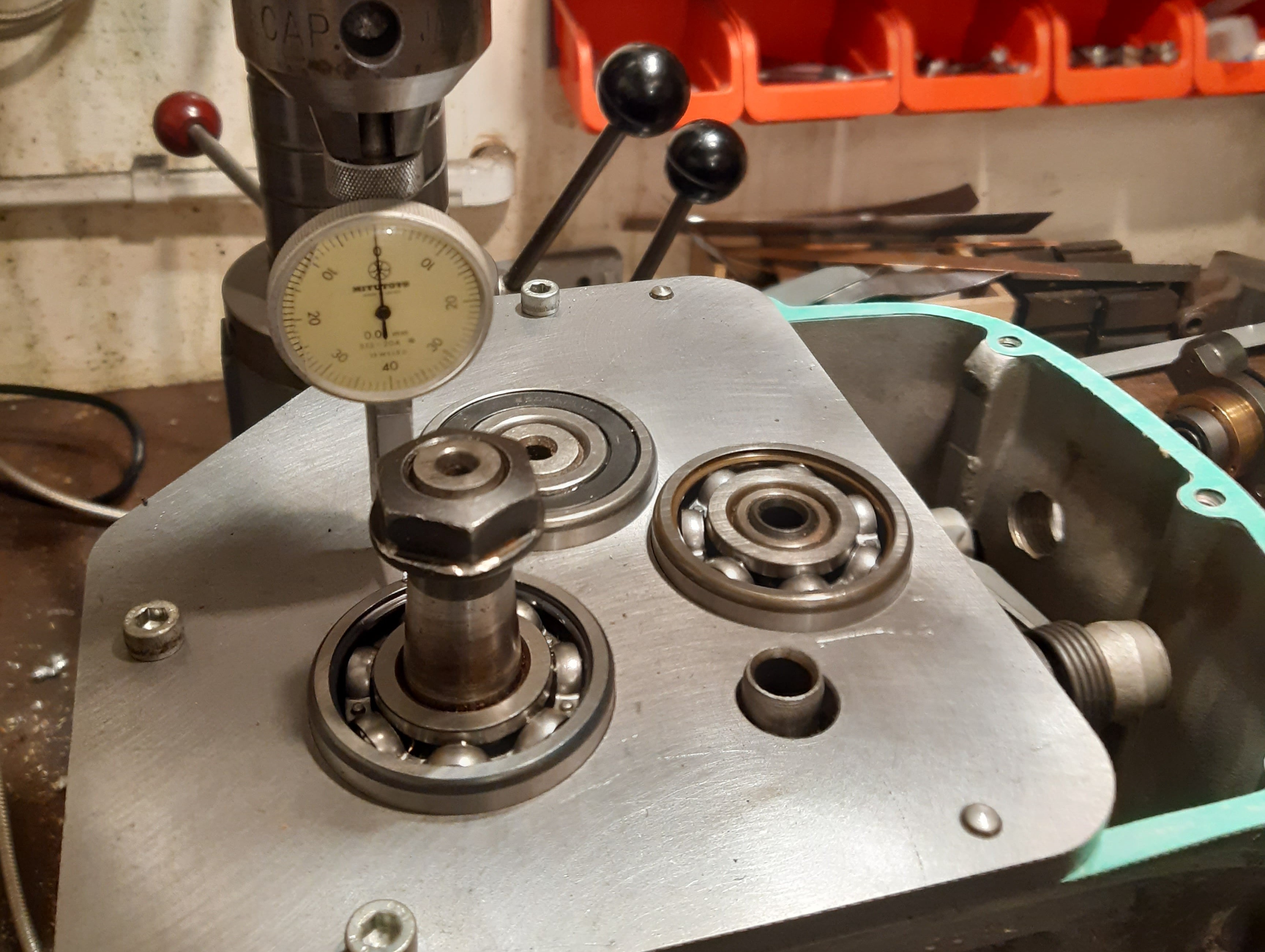
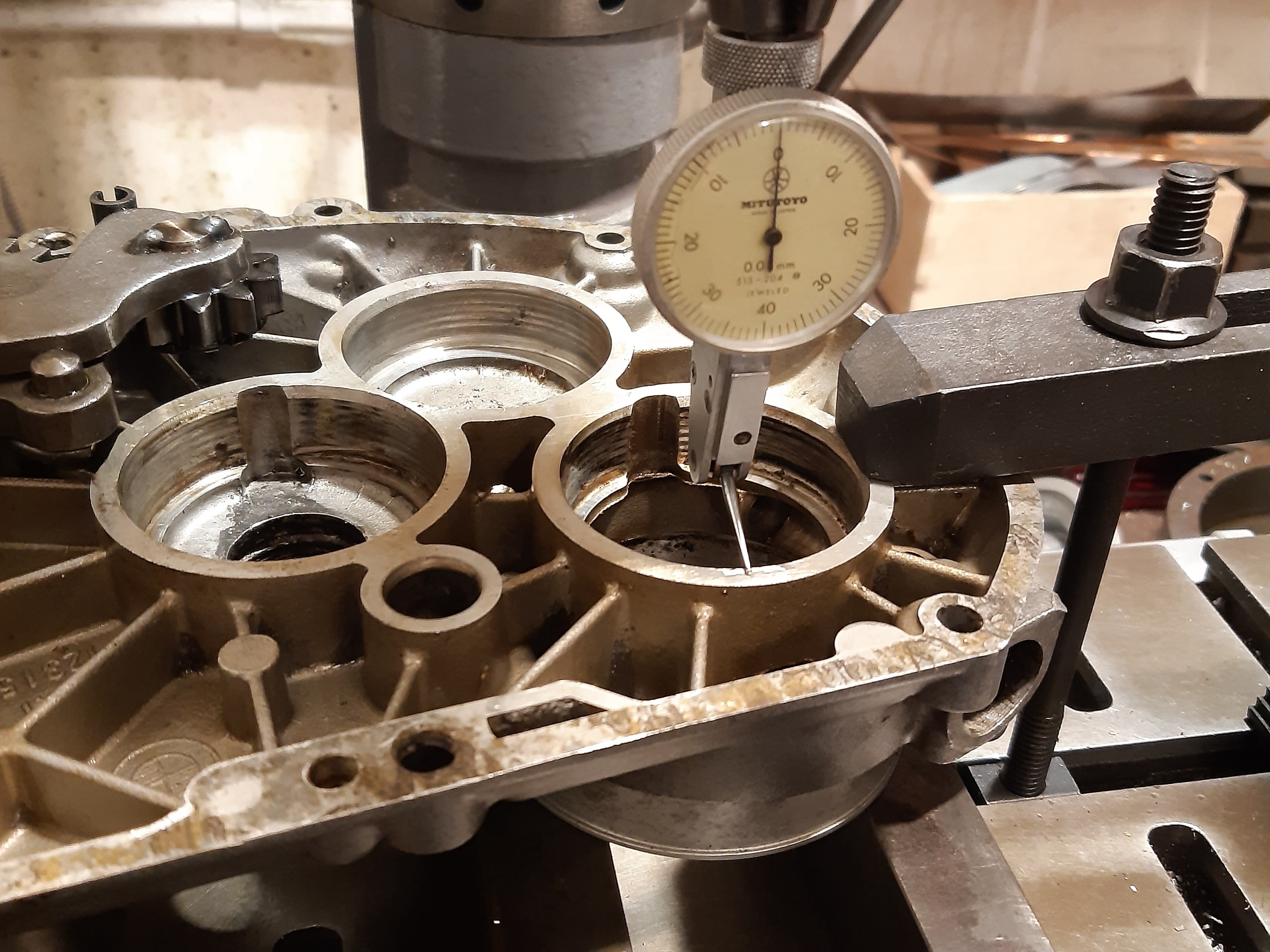
Detailed below is a process to remove the gearbox and replace bearings and seals and check for any other probelms.

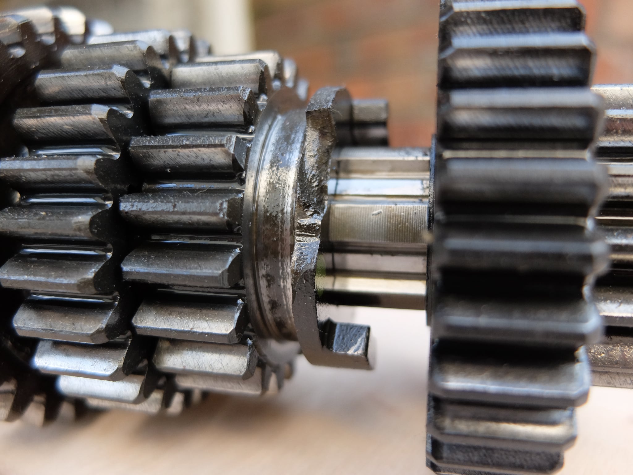
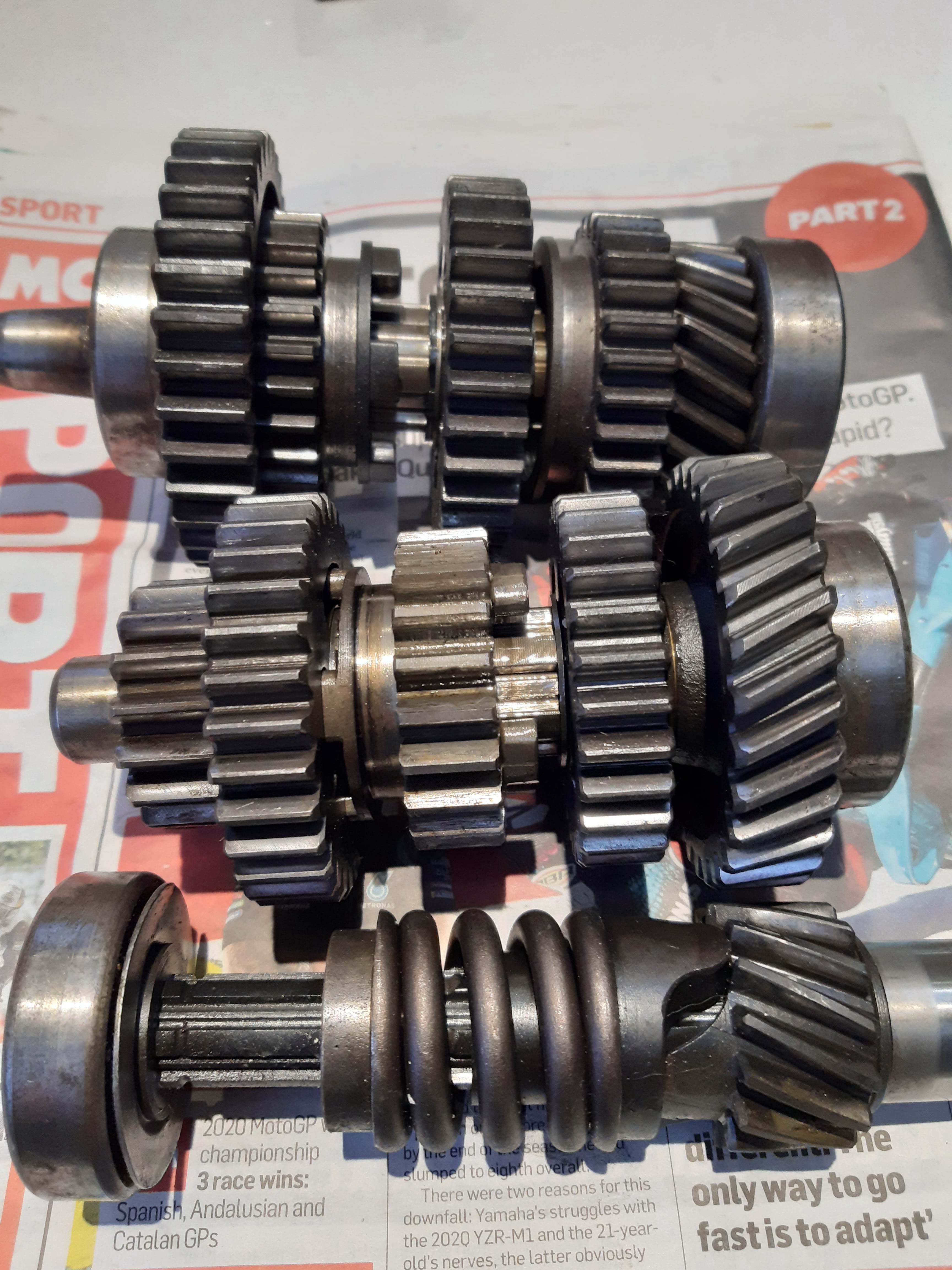
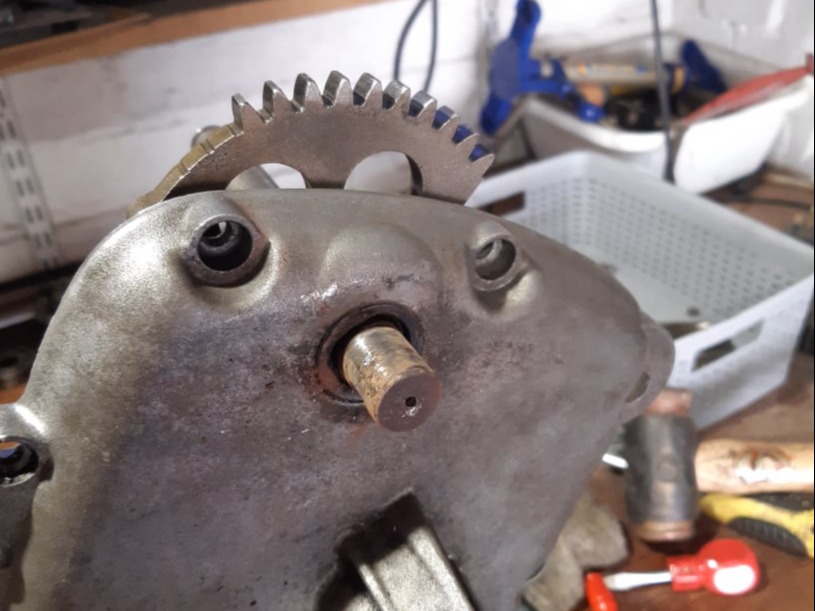
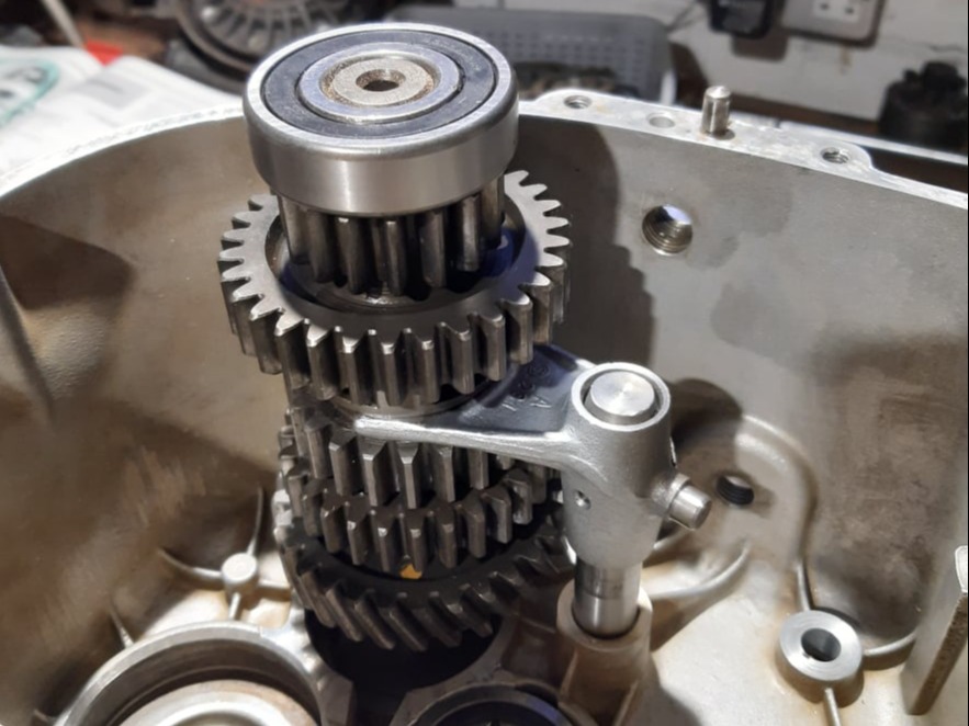
This particular gearbox was an early 5 Speed transmission with optional kick start.

Mobirise Website Builder

Gearbox Removal

The gearbox is held to the engine by just four bolts. However to lift the gearbox free from the clutch splines it is necessary to move the swinging arm back and remove the battery. It is also necessary to disconnect the drive shaft, speedo cable and clutch cable, and the airbox has to be removed.

The bike should be placed on the centre-stand and be made secure before the work starts. It is advisable to remove the tank also for better access.
The rear wheel arch with light assembly should be removed, and the speedo and clutch cable disconnected. 

Mobirise Website Builder

First job is to release the four output flange bolts.
The bolts have twelve faces rather than the usual six and so a 10mm ring spanner is the best tool for the job.
These bolts are stretch bolts and so should be replaced during re-assembly.

Mobirise Website Builder

After peeling back the drive shaft gaiter, the four drive shaft bolts can be undone by holding the back wheel on the brake and undoing each bolt in turn. 

Mobirise Website Builder

The rear wheel arch with light assembly can be removed next, and the speedo and clutch cable disconnected. The brake pedal also needs to be removed

Mobirise Website Builder

The swinging are bolts can be removed using a box spanner to loosen the locking nut and then an Allen key to remove each pivot bolt.
The back wheel should now be free to swing backwards on the rear shocks and can be strapped to the rear frame of the bike, out of the way.

Mobirise Website Builder

The battery should be disconnected and removed complete with mounting tray by undoing the 4 cushioned mounting nuts.

Mobirise Website Builder

The airbox is removed by first detaching the inlets to the carbs; then working on the left side first, the long clamp bolt can be removed, followed by the air filter element. The clamp bolt on the right (shown above) releases the RHS.

Mobirise Website Builder

The clutch arm can be removed by prising the circlip off and extracting the pivot shaft.
Then the arm, piston and thrust bearing assembly should come out.

Mobirise Website Builder

The four gearbox nuts can now be  removed and the gearbox slid from the clutch splines. The box can then be lifted out the left-hand side of the frame as shown.

Mobirise Website Builder

Wherever the gearbox is stored care should be taken not to damage the splines. A simple wooden plate like this works quite well.

Gearbox Diassembly

Mobirise Website Builder

A 24mm socket was used to undo the centre nut on the output drive flange.
Torque on this nut is set to 220Nm, so some effort is needed to free it.
To hold the flange, a tool was made up with 4 holes for the flange bolts and an arm held in the bench vice; but a piece of angle steel with 2 holes may also be used. 

Mobirise Website Builder

A strong extractor tool will be needed to lift the output flange from the drive taper.
A 3 legged puller is an option but only if a steel plate is bolted to the flange first, to give the legs an edge to grip on.

Mobirise Website Builder

Removing the output drive flange......

Mobirise Website Builder

.....followed by the speedo drive.

Mobirise Website Builder

The screws were removed from the gearbox end housing and the hot air gun used to heat the box to about 85 degreesC....

Mobirise Website Builder

...then a soft mallet was used to gradually lift the end cover clear.
On this gearbox with the kick start, it was necessary to rotate the kick start slightly, to clear the gearbox internals.

Mobirise Website Builder

The two shouldered bolts holding the selector mechanism to the housing were undone and the selector cams removed.

Mobirise Website Builder

The input shaft can now be lifted from the roller bearing in the housing.

Mobirise Website Builder

The 1st &2nd and 5th gear selector forks can be removed by sliding the shaft out first; allowing the forks to be separated from the gear train.

Mobirise Website Builder

To remove the two remaining gearbox shafts and the 4rd&4th selector fork, the case was heated to 100 degrees C.
With the gearbox held in the vice the parts were pulled free.

Mobirise Website Builder

Under inspection a number of faults were found with the gearbox.
One of the dogs had broken on the intermediate shaft. Not uncommon on early 5 speed boxes. The dogs were not precision machined but were forged and so often one dog would take all the load.

Mobirise Website Builder

This gearbox also showed pitting on all three of the helical drive gears.

So the decision was made to find a new set of gear internals to fix the box.

Mobirise Website Builder

The new gears came from a later gearbox and without the kick start gear.

Mobirise Website Builder

Each of the bearings was removed using a bearing extractor/separator.
Some simple wooden jaws in the vice were used to help hold each shaft assembly safely.

Mobirise Website Builder

The bearing on the back of the input shaft needs to be extracted without pulling the top-hat and bearing plate off.
1 = Bearing
2 = Bearing plate
3 = Top hat
This photo also shows significant wear on the kick starter gear 😕.

Compatibility issues

Mobirise Website Builder

The new gear set didn't have a kick start gear fitted. To swap the kick start gear over from the original shaft, the top hat was removed using the bearing puller.
Then the cush-drive spring was compressed using the bearing puller to pull the spring closed from the other end of the shaft.
Then the retaining spring ring was removed and the gear too.

Mobirise Website Builder

Another compatibility issue with the new parts was the 5th gear selector fork which had a larger diameter than the original.
The working diameter on the original gear was 47.96mm......

Mobirise Website Builder

....whereas the new gear had a diameter of 49.94mm. So a new selector had to be fitted accordingly.

Mobirise Website Builder

The circlip issue!
There is a known issue which occurred with the introduction of the 5th gear on the /6 bikes.
The 5th gear created an axial load on the output shaft front bearing which could move the bearing forward and make the shaft motion tight.
Some bikes had a circlip to stop the shaft moving in the bearing and some didn't. Some people recommend adding the circlip if these isn't already one there.
A good description of the issue can be found on Anton's site at http://www.largiader.com/articles/circlip/

In addition, the original BMW bearing had no chamber on one side of the inner race to help the circlip work. Modern bearings don't have this so a spring ring was added to help fill the gap.
Regardless of the bike, it is worth putting some attention to this bearing to make sure the shaft doesn't move under load.

Mobirise Website Builder

Kick starter comments
Reading up on how the kick start evolved over the generations of bikes, the fundamental conclusion was that /5 kick starts on the 4 speed box were mostly OK. They could be used regularly without concern. They were derived from the /2 bikes which had no electric start.

However, the 5 speed box was not designed to have a kick start and one was only added after customers demanded it. So it was added in retrospect and suffered a couple of issues.
1. The main kick start spindle was just left to run in the aluminium housing without bushing. Wear occurred quickly and was difficult to recover.
2.The kick start gear on the input shaft had 11 teeth originally and used to wear quickly. The later 14 tooth one was an improvement but some of these were too soft as well.

Selector overhaul

Mobirise Website Builder

To overhaul the selector mechanisms the 3 springs should be replaced along with any circlips and the plastic roller can be upgraded to a bearing.
The image above shows the selector plates set for first gear.
This is clear from the cam roller position in the left hand plate. The tooth alignment (circled) is noted for reassembly.

Mobirise Website Builder

With the pivot circlips removed the ratchet mechanism with the 3 springs are accessible.
Each lever can be removed and each spring replaced in turn.

Mobirise Website Builder

It is important to get the segment shaft spring the correct way round.
The images below should clarify.
When correctly fitted the spring arms will naturally sit up against the segment plate.

Mobirise Website Builder

If the spring is not fitted correctly the arms hang down away from the segment plate and slip out of place easily.....

Mobirise Website Builder

.... Just flip the spring over to correct this.

Mobirise Website Builder

The cam roller bearing is a direct replacement for the plastic roller.

Kickstart Overhaul

Mobirise Website Builder

On the inside of the end plate the circlip can be removed along with the shims to release the small pinion gear arm.
This is not necessary to remove the kick start from the cover, but allows for inspection of the parts.

Mobirise Website Builder

The kick start lever can be removed by undoing the cotter pin and driving it out and then drifting the lever from the shaft.
For both operations, some heat maybe be needed to free things up.

Mobirise Website Builder

With the kick start spindle removed it was found to be a loose fit on the worn hole. So a stainless bush was machined up and fitted to the case.

Mobirise Website Builder

New bush 17mm ID and 15mm long

Mobirise Website Builder

Bush in end cover. 20mm OD

Mobirise Website Builder

A new seal was pushed into the case before refitting the kick start lever and mechanics.

Mobirise Website Builder

Gearbox Reassembly

New bearings need to be drifted into place on the shafts aside from the input shaft bearing at the engine end. This bearing should be placed into the gearbox housing.

Bearing specifications are given in the table on the right.

The sealed intermediate bearing was only available with both rubber shields so one was removed with a pick before fitting.

The bearing was fitted with the open side nearest the gears.

Mobirise Website Builder

To do a full overhaul, bearings should be replaced along with gaskets and input/output and shifter seals.

It is wise to replace the selector springs as historically there has been some poor quality batches produced and if one breaks the rider will be stuck in whatever gear they are in.

Mobirise Website Builder

The man case needs to be heated to about 100 degrees C to allow the bearings to drop into place.
The input shaft bearing is fitted as shown and the two oil baffle plates for the intermediate and output shaft.

Mobirise Website Builder

The 3rd / 4th gear selector fork can be placed on its shaft and engaged with the intermediate gear cluster. However at this stage, the shaft is not located in the end casing, but is left to one side to allow room for the output shaft.

Mobirise Website Builder

The output shaft can be added to the assembly and the intermediate shaft then rotated towards it to get them to mesh.
The both shaft bearings should then drop into the gearbox casing.

Mobirise Website Builder

With the remaining shift forks orientated as shown they can be fitted to connect with the output shaft in the gearbox.

Mobirise Website Builder

The flat on the 5th gear fork being at the open end of the gearbox.

Mobirise Website Builder

The selector mechanism set to neutral position can be bolted into the gearbox, ensuring all 3 shift forks engaged in their slots on the cam plates.

Mobirise Website Builder

It should then be possible to drop the input shaft into place.

Mobirise Website Builder

Each shaft should be measured for shimming; the target to set each shaft with a maximum end float of 0.05mm.
To measure the shafts in the gearbox an 8mm plate was laser cut to create a datum and the plate was bolted into place over a new gasket to account for gasket compression.
Then the edge of each bearing was measured down to the plate surface.

Mobirise Website Builder

Similarly the depth of each bearing seat is needed, measured from the gasket surface.

In this case the DRO on the milling machine was used but a depth micrometer would also be suitable.

Mobirise Website Builder

The difference between the bearing pocket depth and the first bearing measurement (plus the plate thickness) can now be used to calculate the required out shims.
However, the intermediate shaft also had an oil baffle to add to the calculation. BMW shims are available in:
0.2mm, 0.28mm, 0.38mm and 0.5mm
However, from other bearing suppliers there were also:
0.1mm, 0.2mm, 0.3mm, 0.5mm, 1mm, 1.5mm

The chosen shims are shown in the yellow column. This would give slightly more clearance than the specification, but better than being too tight.
0.5mm and 0.38mm shims were previously taken from the gearbox so just 3x 0.2mm shims were needed to make up the correct stack of parts.

Mobirise Website Builder

The shims and the oil baffle can now be stuck to the bearing ends with a dab of grease.
Then the end cover needs to be heated up and dropped into place, aligning the dowels and ensuring the gasket is flat.
A tap with a rubber mallet might be  needed to get it to seat.

Mobirise Website Builder

The end cover should be torqued down to 9 Nm

Mobirise Website Builder

The shifter seal, input shaft and output shaft seals need to be drifted into place with a suitable socket. The large output seal orientation is as shown, and this was drifted with a piece of plastic tube.

To finish, the output flange should be replaced and torqued down to a mighty 220Nm.
If the input shaft is stiff to turn, a sharp tap with a soft mallet will often take off any preload of the bearings caused by clamping the rear cover on.

HTML Website Maker