Mobirise Website Builder

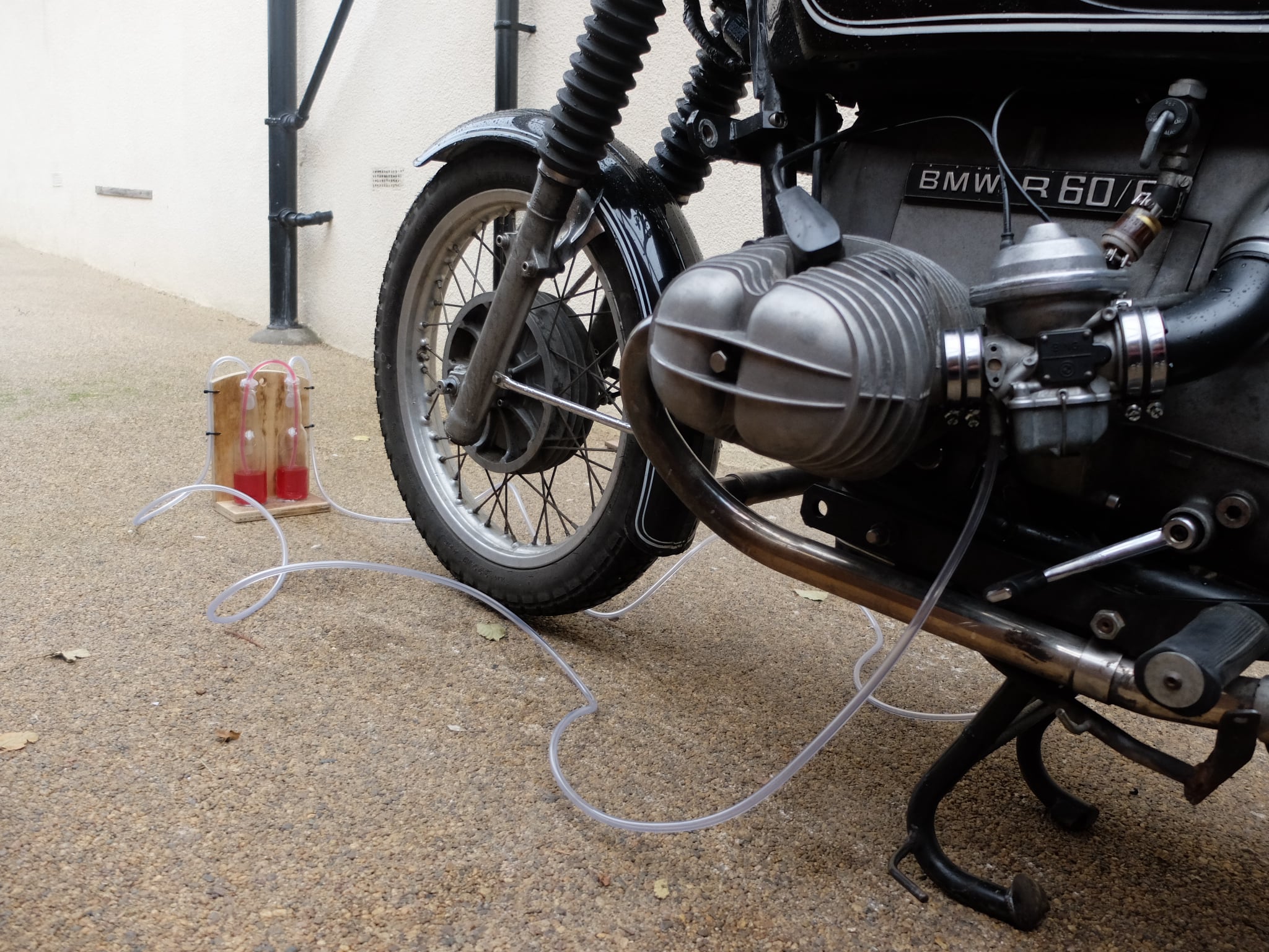
Converting the R60/6 to CV carburetors

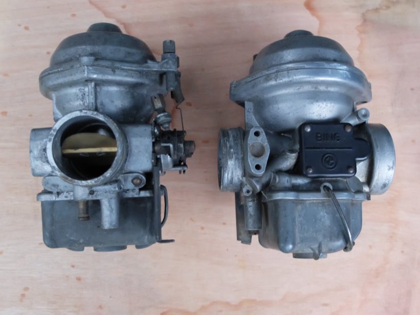
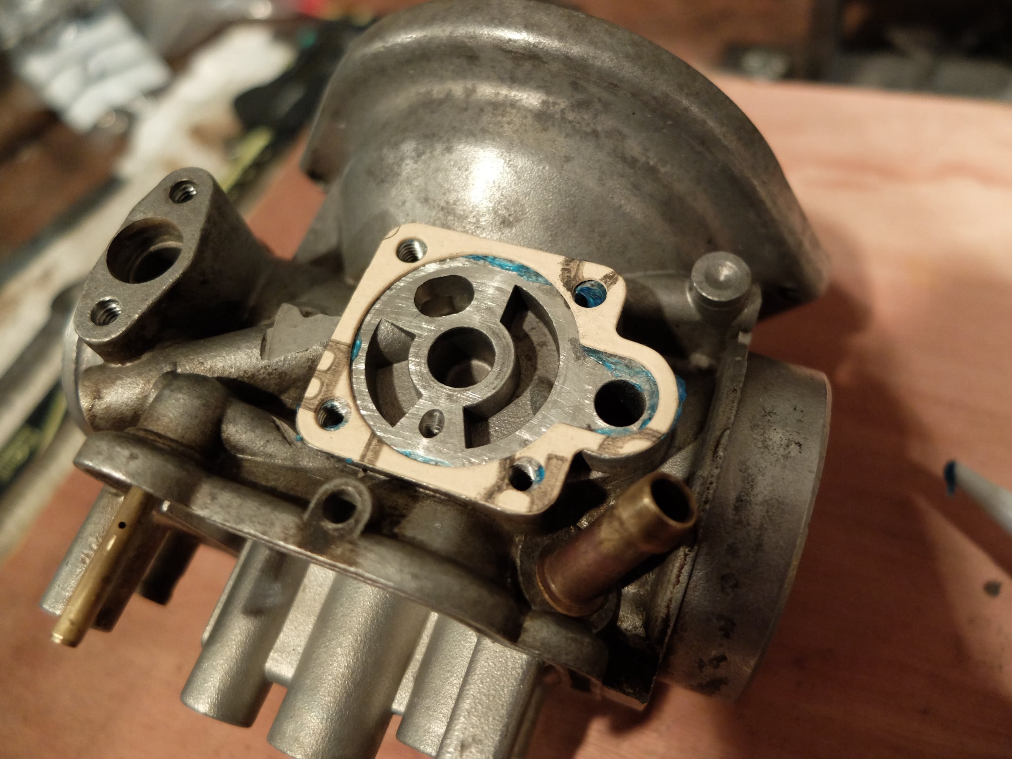
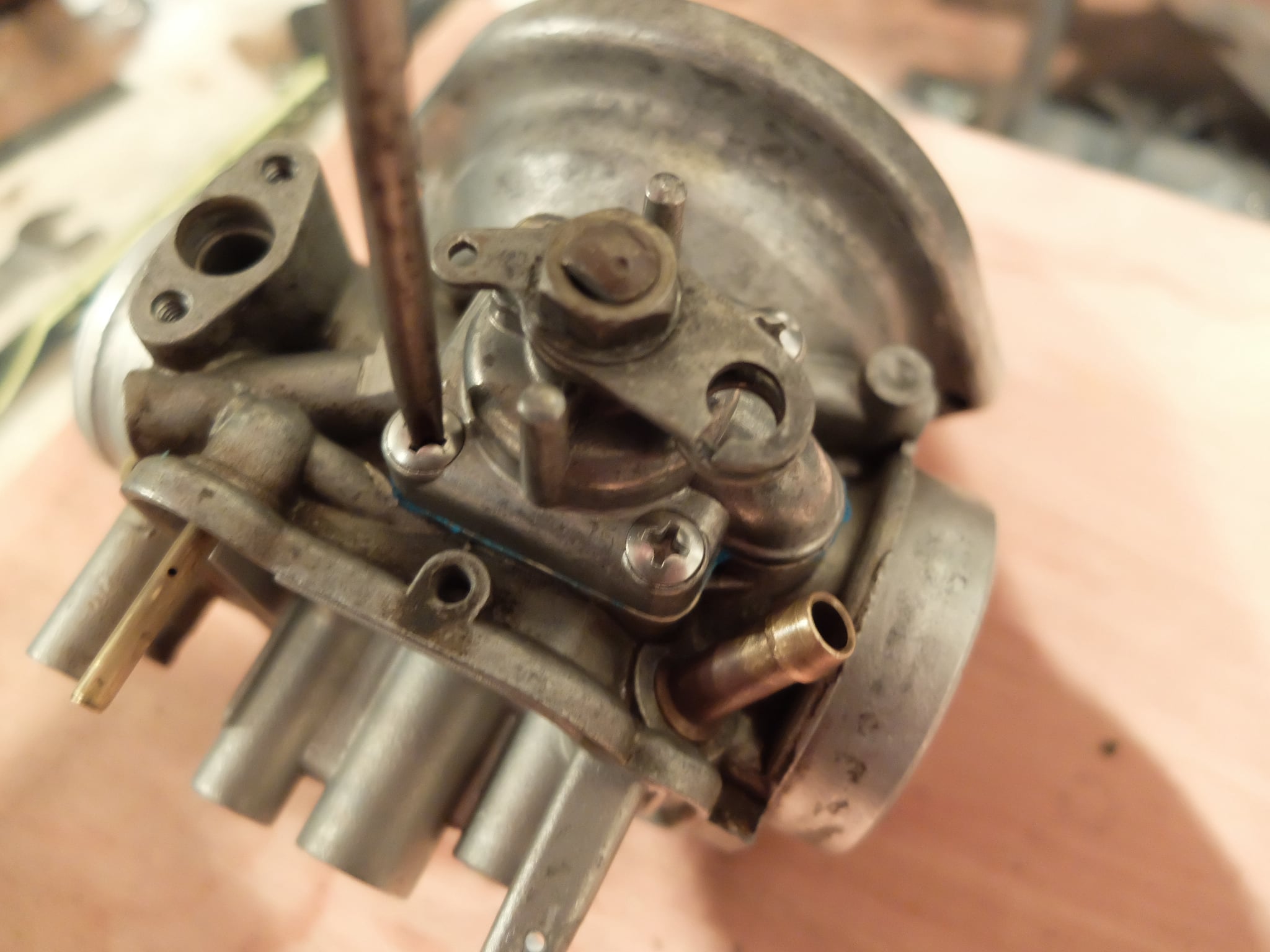
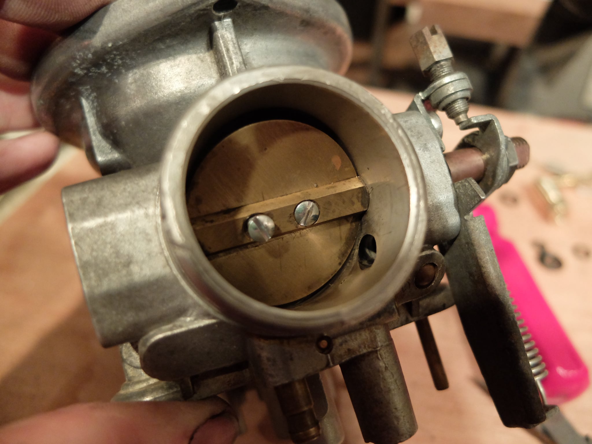
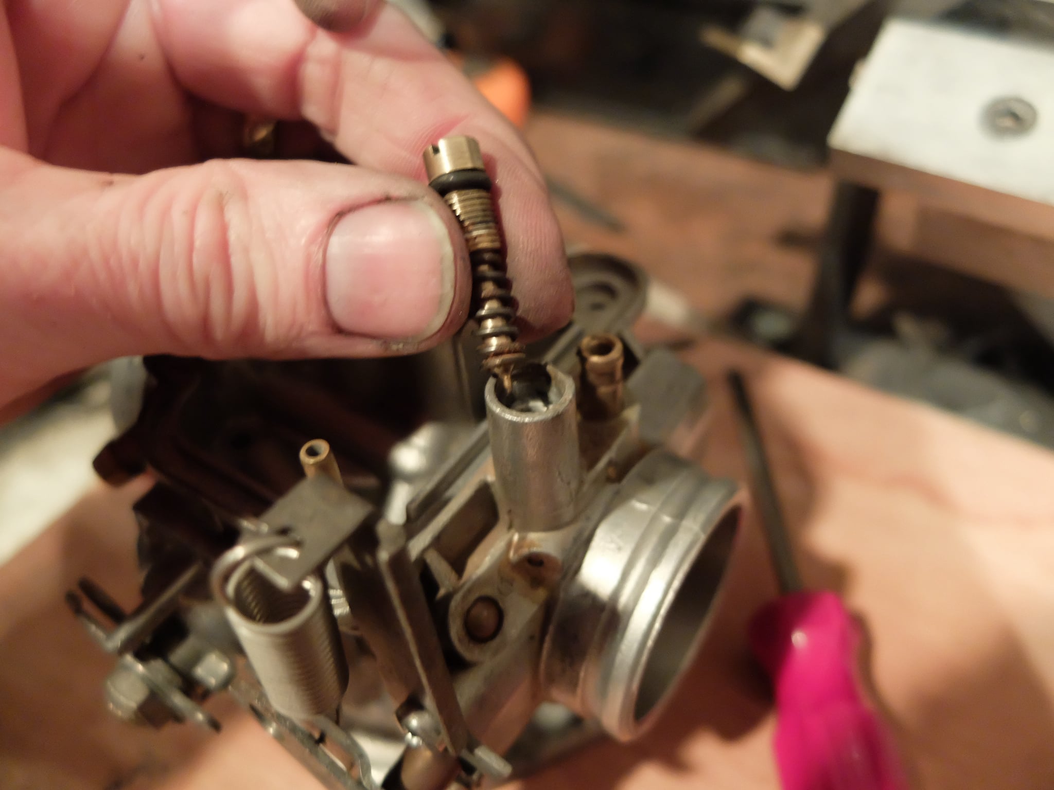
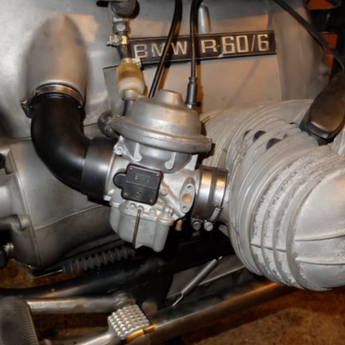
As standard the R60/6 bikes were equip with Bing 28mm sliding carburetors.

These were probably adequate when new, but 40 years and a few bodged fixes later, this bike was difficult to tune and not responsive to the throttle.
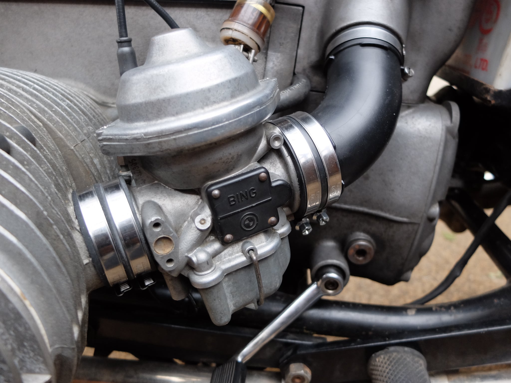
The decision was made to convert it to the later CV carbs.

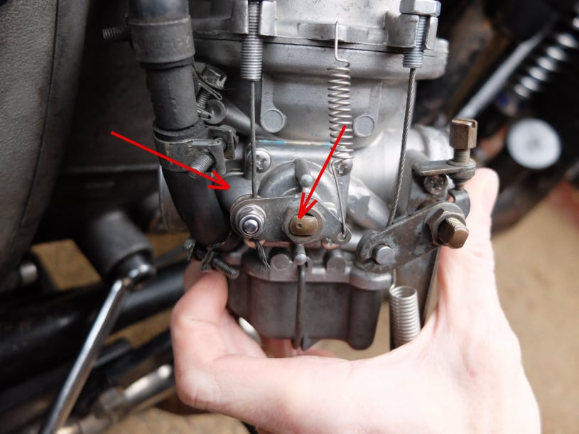
It has been reported that this conversion was popular with the Greek police. Not for performance issues but because of vapour lock, caused by the hot weather and the fact that the sliding carbs were not well insulated from the hot cylinder block.
The conversion they used, was to fit Bing CV 32mm carbs from the R80 bikes and so this was the modification chosen for this R60.

Mobirise Website Builder

A pair of second-hand carburetors were sourced. They were part numbers :
Left 64/32/305 13 111 337 4 35
Right 64/32/306 13 111 337 4 36

The proposed jetting was to be:
45 pilot jet BMW part no. 13 111 336 924
145 main jet BMW part no. 13 111 261 703
2.64 needle jet in highest position BMW part no. 13 111 335 744

The following images show the reconditioning of the carbs which had new diaphragms, new O-rings, new needles, gaskets, atomizers and springs.

Carburetor reconditioning

Mobirise Website Builder

The carburetor service kit contents are shown here.
These days it is worth sourcing a kit compatible with E10 petrol.

Mobirise Website Builder

The enrichers parts are shown here.

Mobirise Website Builder

During reassembly - check that the tapered slot of the enricher disc is at the top as you fit it to the main carburetor housing. If it isn't you may have left and right enrichers mixed up.

Mobirise Website Builder

This image shows the enricher gasket.....

Mobirise Website Builder

....and the enricher installed with stainless screws.

Mobirise Website Builder

When attaching the enricher to the carb body - check that the dot on the enricher shaft is pointing towards the inlet channel of the housing. (See arrows).

Mobirise Website Builder

This image shows the correct location of the O-ring on the throttle spindle.

Mobirise Website Builder

The butterfly position is important to ensure it fully closes to avoid a fast idle. Note that the edge is chamfered so that it only seals properly in one orientation. Some fiddling is required to get it to sit right. Shine a light from behind to check for a good fit.

Mobirise Website Builder

The mixture screw and spring. The initial setting is to screw it fully home and then back out 3/4 of a turn.

Mobirise Website Builder

Correct stack of main jet parts.

Note that above the mixture tube there is often black gunk which can be mistaken for the remains of an O-ring, but there is no O-ring there. The O-ring shown fits into the recess of the mixture tube.

Mobirise Website Builder

Installing idle jet with O-ring.

Mobirise Website Builder

Float needle assembly with retaining wire/clip.

Mobirise Website Builder

The float arm tab needs to be carefully bent so that needle valve to shuts just as the float top and carburetor housing ware parallel.

Mobirise Website Builder

The float bowl has a jet for the enricher circuit. The hole (arrowed) must also be clear.

Mobirise Website Builder

New main jet needle was installed by pushing and rotating clockwise into the spring clip. The needle top has 90° notches so you can feel the 4 height positions.

Mobirise Website Builder

A main diaphragms are secured to the piston with 4 screws. Note the location tab that gives the piston its orientation.

Mobirise Website Builder

Likewise there is a feature on the outer rim to locate in the carburetor body.

Mobirise Website Builder

The carb top with spring is held with two screws. After installation the free motion of the main piston must be checked to ensure no tight spots.

CV Conversion

Mobirise Website Builder

To fit the CV carbs to the cylinder, new inlet stubs were machined from 303 stainless. These had a thread of
32 x 1.5mm and a shoulder of 43mm to connect to the carbs.

Mobirise Website Builder

The full dimensions are given here (click for PDF).
It was found necessary to remove the end thread, to get the inlet to pull up fully into the cylinder head.

Mobirise Website Builder

The old inlet stubs were a tight fit in the cylinder. The bike was run to warm everything up and then a large stilson wrench was used to free up the stub.
Plumber's pliers (shown here) were then used to unscrew the inlet.

Mobirise Website Builder

The new inlets were screwed into place using the plumber's pliers again.

Mobirise Website Builder

To connect the carbs to the air box the parts shown on the left were used. These were R80 parts. Specifically......
Left intake tube. BMW no:13 72 1 258 059
Right intake tube BMW no:13 72 1 258 060
Stepped joining collar (x2)
BMW part no. 13 72 1 257 395 

Mobirise Website Builder

The carbs were attached to the cylinder head with BMW part: 13 72 1 254 654.
However these parts were shortened by 5mm to make everything fit without a strain.
To cut the tube length square, it was hose clamped to a bar in the lathe and then scored with a knife (on the underside so the knife was dragged aware from the operator).

Mobirise Website Builder

The original choke cables were reused with a suitable cable clamp on the end to join to the enricher lever.
The clamp was BMW part 13 11 9 057 338
However new throttle cables had to be ordered to give the correct fitting to the new butterfly lever assembly.

Mobirise Website Builder

5x Large hose clamps (40mm -> 60mm) were used on both sides to make connections air tight.
Large hose clamp BMW Part No.
07 12 9 952 123

Mobirise Website Builder

The bike was started by setting the mixture screws out by 3/4 of a turn.
Following a ride to warm the bike up the carbs were balanced using a manometer between the vacuum ports to measure relative performance. Information on this process can be found here.

No Code Website Builder