Mobirise Website Builder

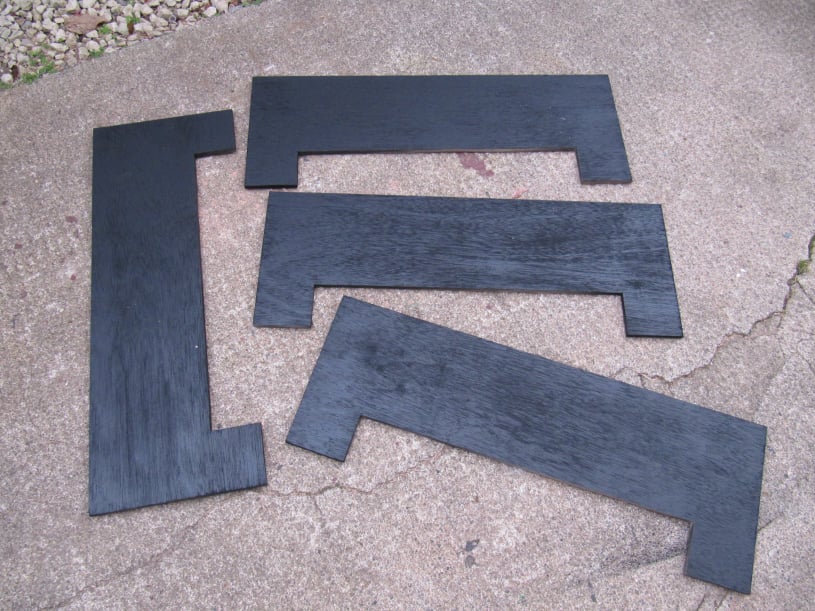
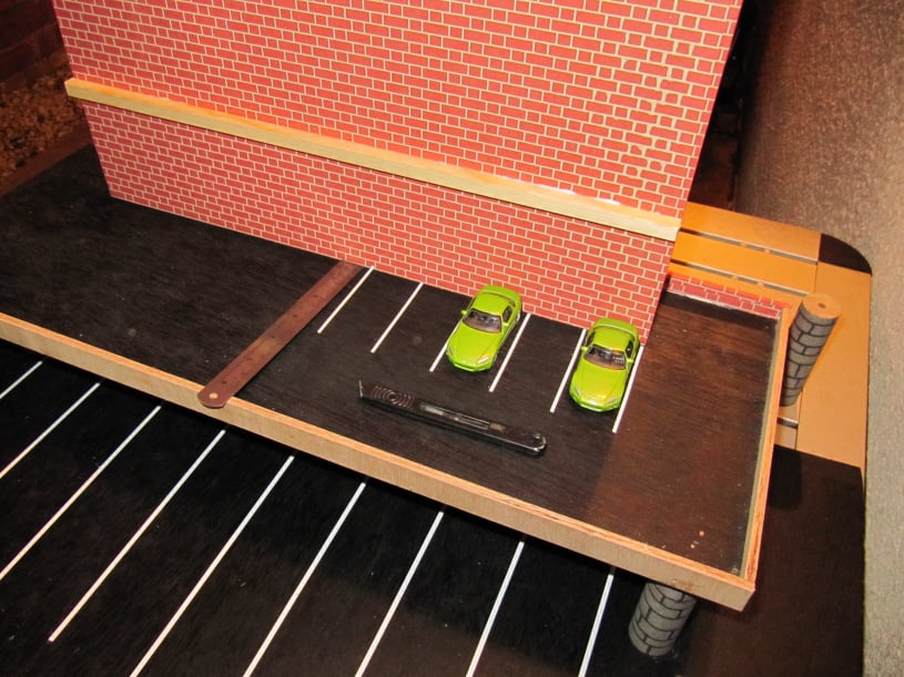
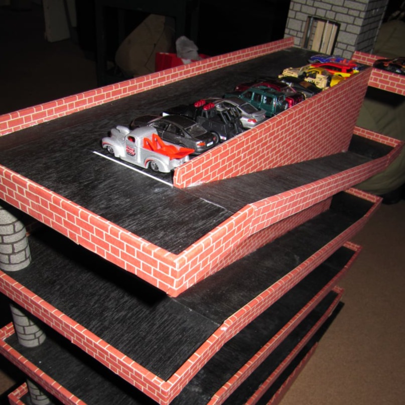
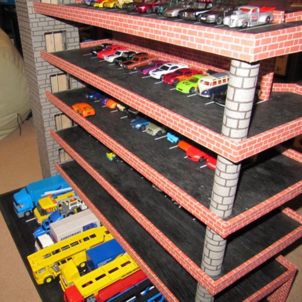
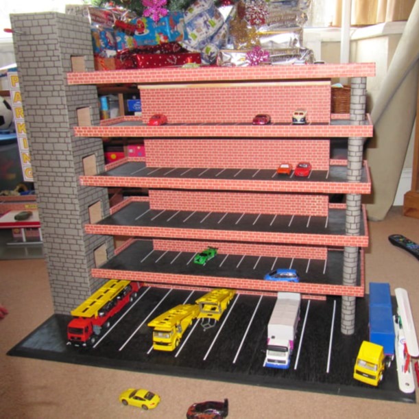
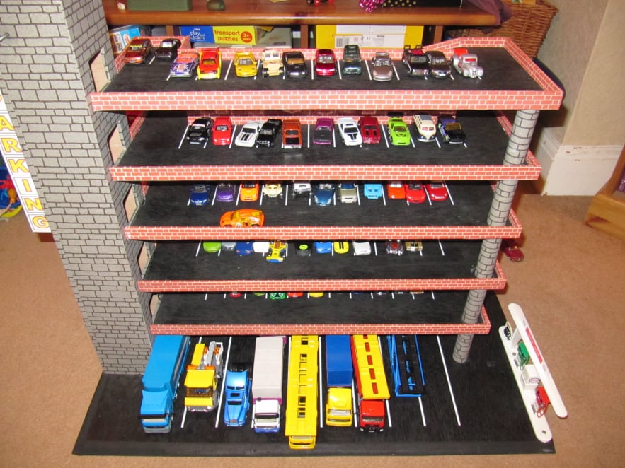
Parking lot. A Multi-Story Carpark

This parking lot was made to accommodate a collection of toy cars.
It comprised of five upper decks for cars and small vans and a larger lower deck for trucks and lorries.
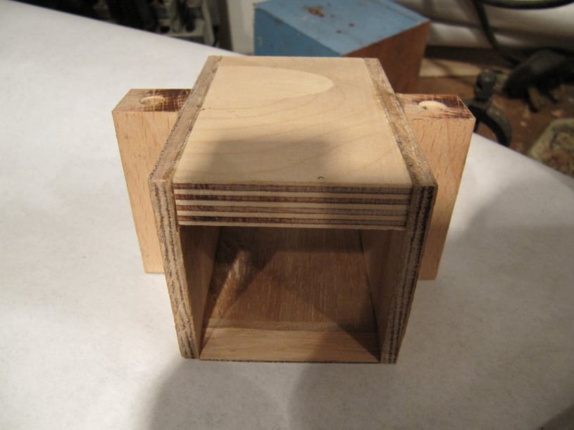
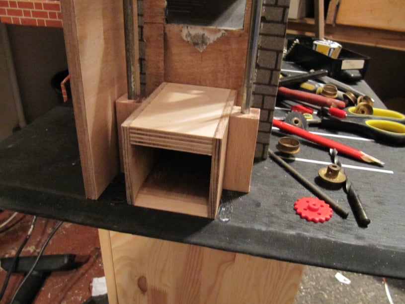
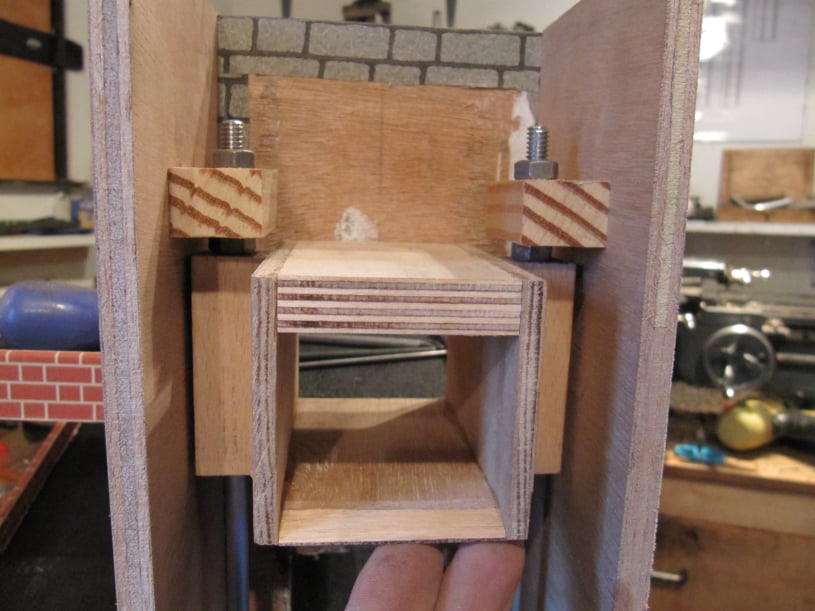
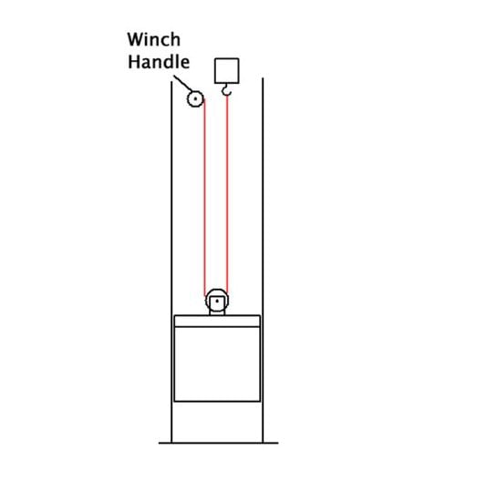
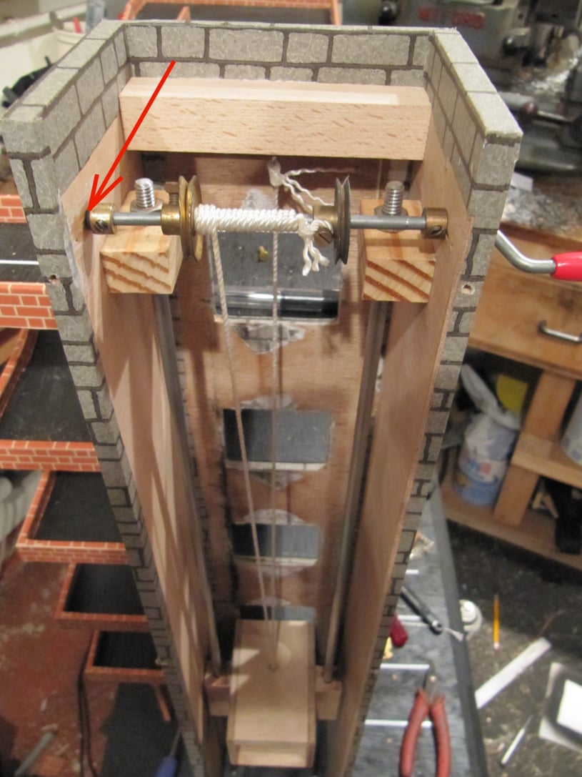
The upper decks were accessed by both a ramps at the rear, and a simple elevator on one side.
A service centre offering fuel, oil and tyres was included on the right hand side of the ground floor.

Mobirise Website Builder

The upper decks were made from 9mm plywood and had the profile shown on the left. They were finished in matt black paint.
Each one was 220mm wide by 600mm long.
The cut out was used to house the ramp access between the levels. This cut-out was 70mm wide and 440mm.

The elevator would be constructed in a separate tower on the side, to keep the deck profiles simple.

Mobirise Website Builder

To start construction. A wall the correct width to fit in the deck cut-out was attached to the base. The base was 800mm lond and 400mm deep, chamfered on the front and left hand side. This was covered with brick paper stuck on with watered down PVA glue.

The base had lorry parking bays marked out with Trim-line self adhesive lines. Lorry bays were 60mm wide.

Mobirise Website Builder

Each deck was finished with parking bays marked out, side walls fitted and access ramp in place, before moving on to the next deck. This process was followed to allow easier access to do the work.

Each deck was held in place with a baton along the main wall and a single pillar in the right hand front corner. The pillar was made from an old broom handle wrapped in contrasting stone paper. Separation between the decks was set to 100mm; more than was required by scale, but it would give good access to play with the cars.

Mobirise Website Builder

The elevator was a simple box construction made from plywood off cuts. It was made 90mm deep by 50mm high and 50mm wide.
The lower plate was chamfered at the front edge to allow smooth access for the vehicles.

Each side, a block of hardwood was glued in place. This was drilled central and parallel right through with a 5/16" drill.

Mobirise Website Builder

The elevator was designed to run on two vertical bars of 1/4" steel which were to hand. This bar was threaded 1/4" UNC on both ends.

The elevator car was used as a template to drill the base of the parking lot. These holes were tapped 1/4" UNC to match the rod.

The side of the elevator shaft facing the floors had holes cut in it to line up with each of the decks. It was then finished in stone brick paper and glued in place. The sides were cuts to suit and also finished in the stone paper.

Mobirise Website Builder

At the top of the shaft the rods were held in place with wooden blocks glued to the sides. These blocks had oversized holes drilled in them so that the rod position could be adjusted. To get the final position of the rods, the elevator was raised to the top of the shaft and then the nuts were tightened to grip the block. This ensured the rods were as parallel as possible for the whole height of the shaft.

Mobirise Website Builder

Originally it was planned to use a chain and sprocket mechanism on both sides of the elevator car to provide a positive drive in both the upward and downward direction.
However this system was plagued with jamming problems. It was complicated and over-constrained.

So in the end a simple pulley and winch arrangement was used. Vintage Meccano parts were used to make the winch and crank mechanism.
This meant that the elevator car was reliant on gravity to maintain cable tension for the down direction, but this proved OK in practice.
Friction was added to the winch shaft by pinching an O-ring between one axle end collar and the side of the shaft. This friction was set so that the elevator would hold a position in the shaft and not fall to the bottom, even with a car loaded. The picture below shows the location of the O-ring (arraowed).

Mobirise Website Builder

This photograph shows the finished winch mechanism.

Two pulleys were included on the shaft just to guide the coil of cord.
The cord length was set so that with the elevator at the lowest position winding the handle in either direction would lift the car.

The front face and top of the elevator shaft were screwed in place rather than glued so that the mechanism could be maintained.
With the metal bars polished up and aligned corrected the elevator car travelled up and down with ease.

The friction O-ring is arrowed.

Mobirise Website Builder

Mobirise