Mobirise Website Builder

Turning Locomotive Wheels

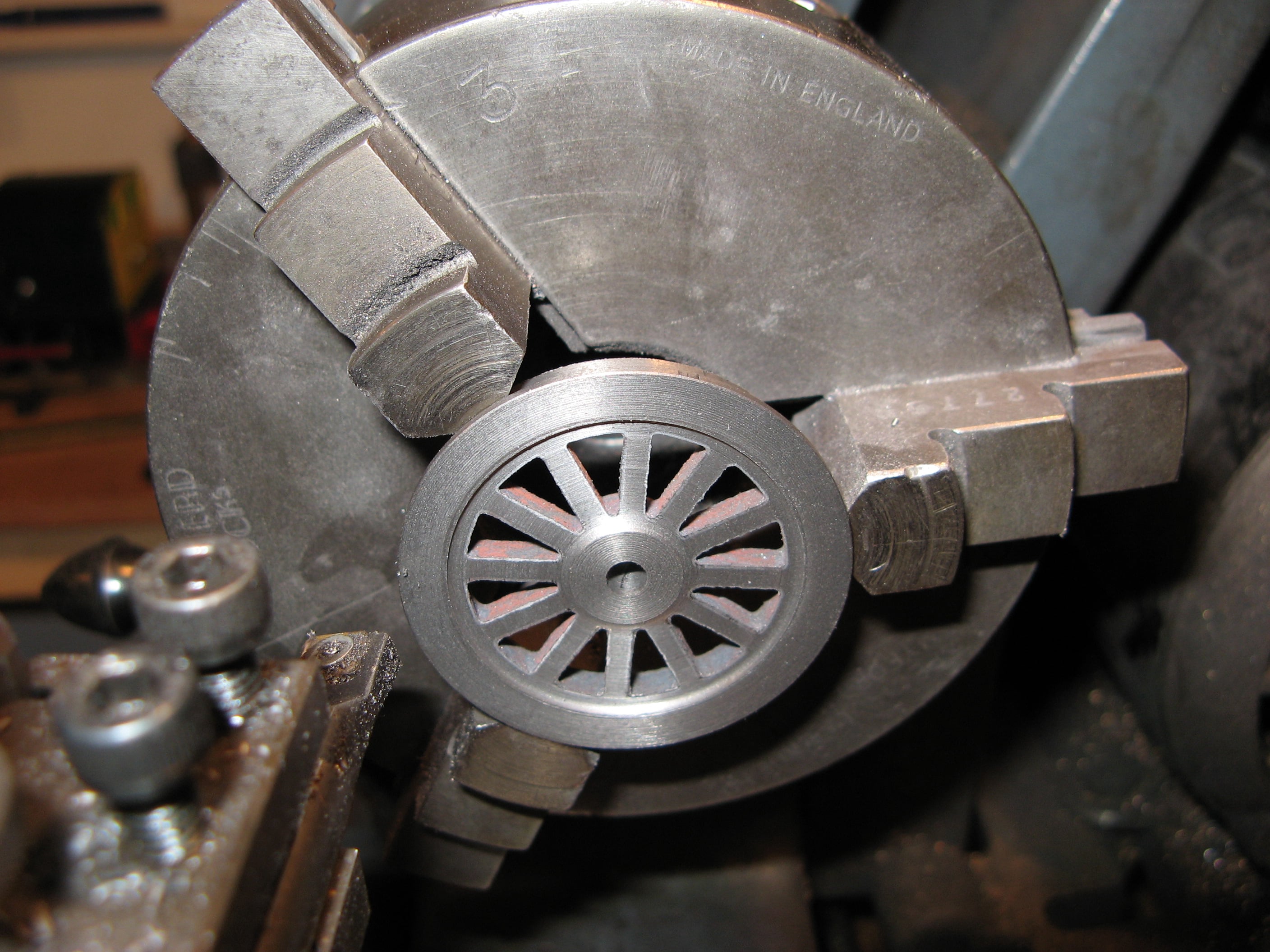
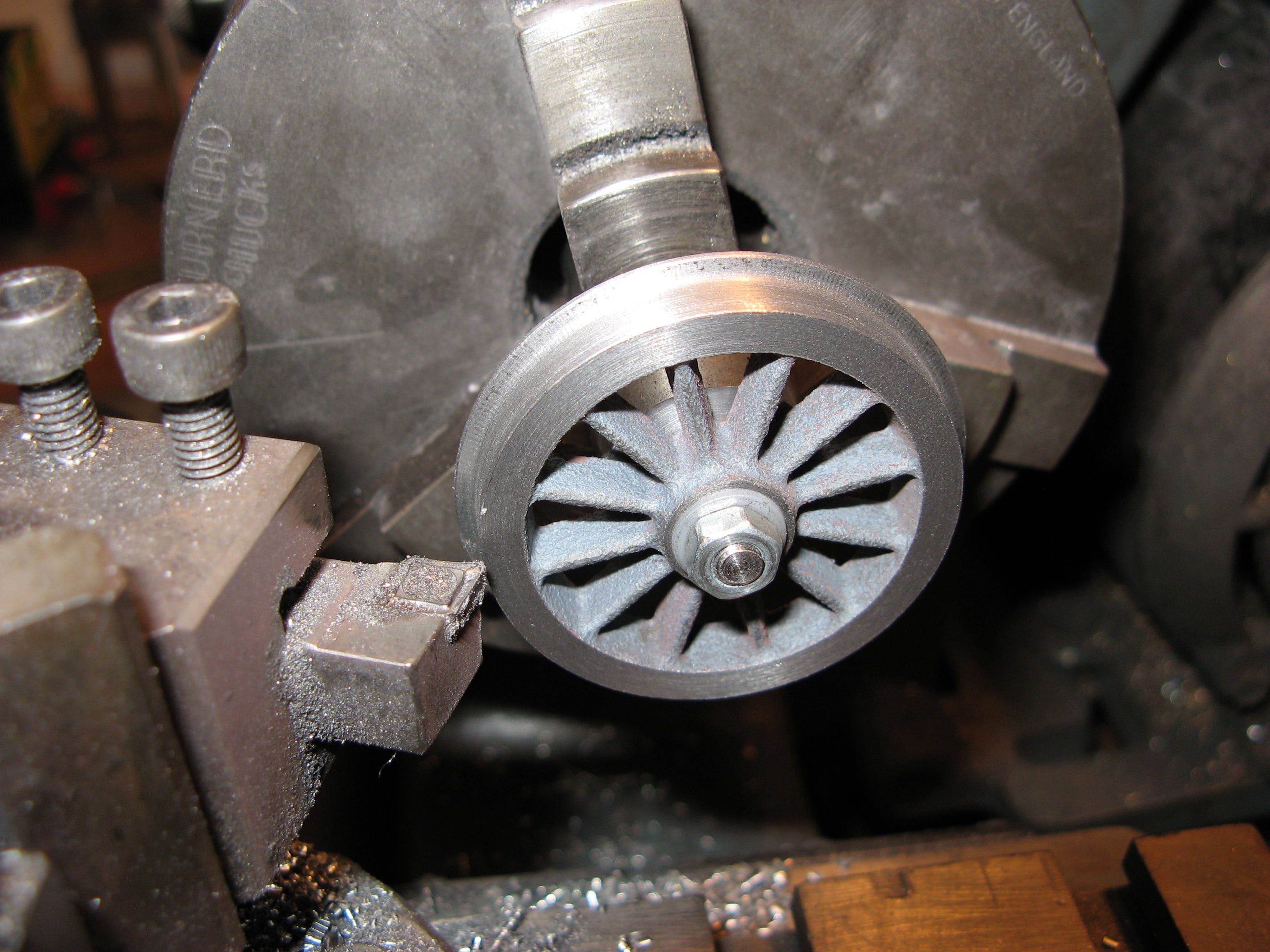
This page describes a process used to turn locomotive wheels to the identical sizes and with true running surfaces.
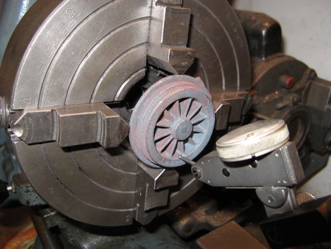
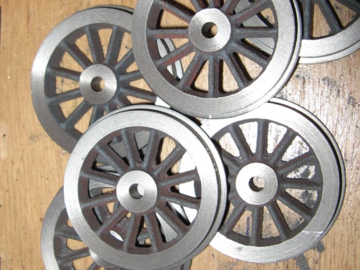
The wheel used in this example was a small Gauge 1 tender wheel about 40mm diameter but the same process can be used on wheels of any size.
When machining a set of wheels it is best if all wheels complete each step, before moving on to the next process. This ensures that the wheels in the set, have the same dimensions as each other.
The same approach can also be applied to ensure a flywheel runs properly true.

Mobirise Website Builder

The wheel blank or casting has to be set up in the 4 jaw chuck so that the inner rim is running true, both axially and radially.
This can be a time consuming process but is necessary to ensure the unmachined surfaces run true and look correct when the wheel is turning.

Mobirise Website Builder

The wheel may also need some packing behind it because it must protrude from the jaws to enable an area of tread to machined. Although not the whole tread width needs to be accessible at this stage.
The tread should now be machined slightly over size and with a square profile. This 'square tread' will be used to hold the wheel in the chuck to machine the back face later on.

Mobirise Website Builder

Without moving the wheel from the chuck, the centre boss should be machined to the correct height and the axle hole should be centre-drilled, drilled and reamed to final size.

Machining the tread, hole, rim and boss all in one setting ensures that they are all concentric.

Mobirise Website Builder

Once all wheels have had the square tread profile machined, they can be placed in the 3 jaw chuck. They should be clamped on the square tread section and tapped lightly into place so that the rim is up against the chuck jaws. In this setting the rear of the wheel can be machined to give the wheel its final thickness and any boss required on the rear of the wheel can be turned to the required diameter and thickness.

Mobirise Website Builder

Depending on the wheel design and the casting dimensions it may be necessary to recess the back of the wheel as shown here to expose the spokes.
If there is any run-out in the 3 jaw chuck (there is usually some) then the boss and rear of the rim may will not be concentric, but these areas are not visible in the finished loco and so are not usually a problem. If you require this to be more accurate then the 4 jaw can be used.

Mobirise Website Builder

Once all wheels have reached this stage, an arbor should be made in the 3 jaw chuck and machined to the diameter of the axle hole and threaded for a nut.
To machine the tread detail, the top slide can be set to cut the tread angle and the tool can be set in the tool post to cut the rim angle at the same time.
Using the top slide and cross slide indexes, all treads can be cut to the same diameter and width. Light cuts must be taken with the wheel on the arbor to prevent damage to the spokes and to avoid the wheel slipping against the clamping force of the nut.

Landing Page Maker