Mobirise Website Builder

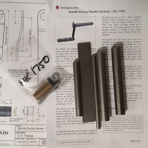
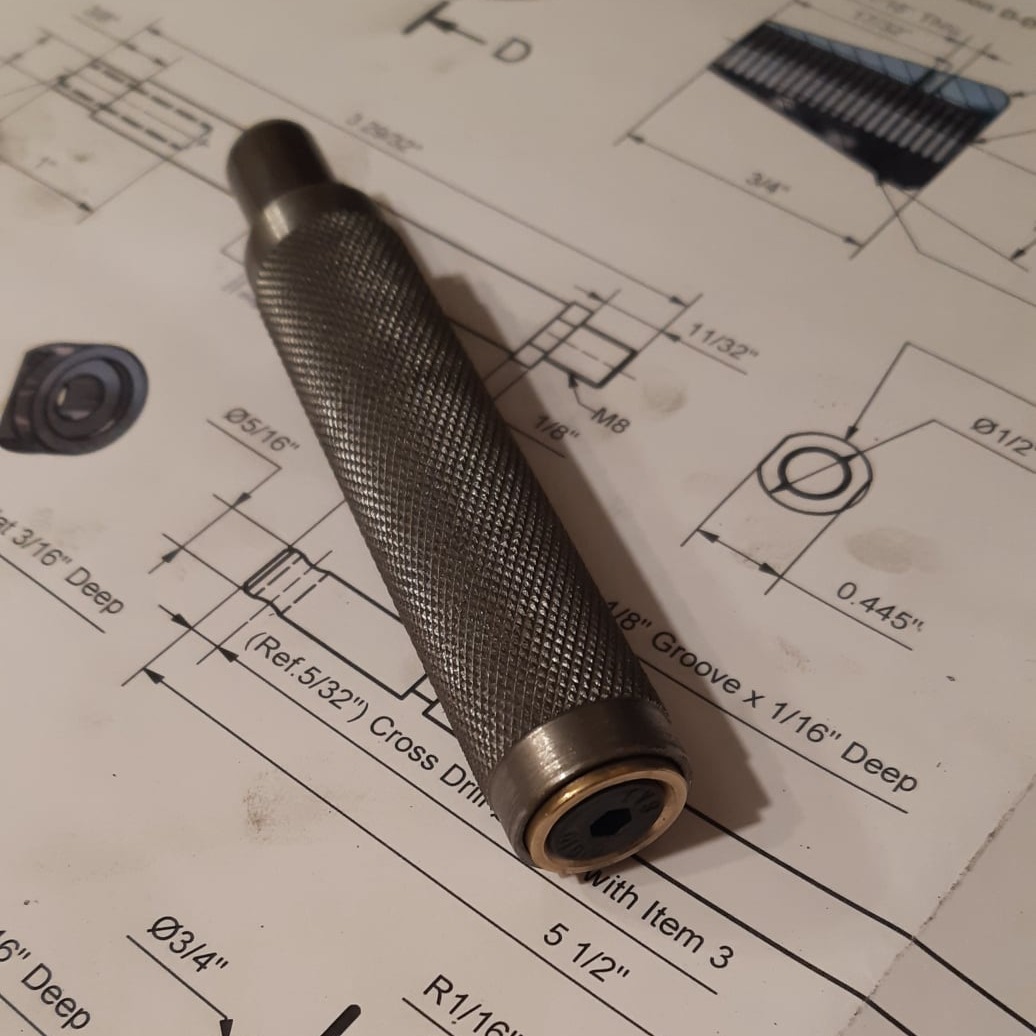
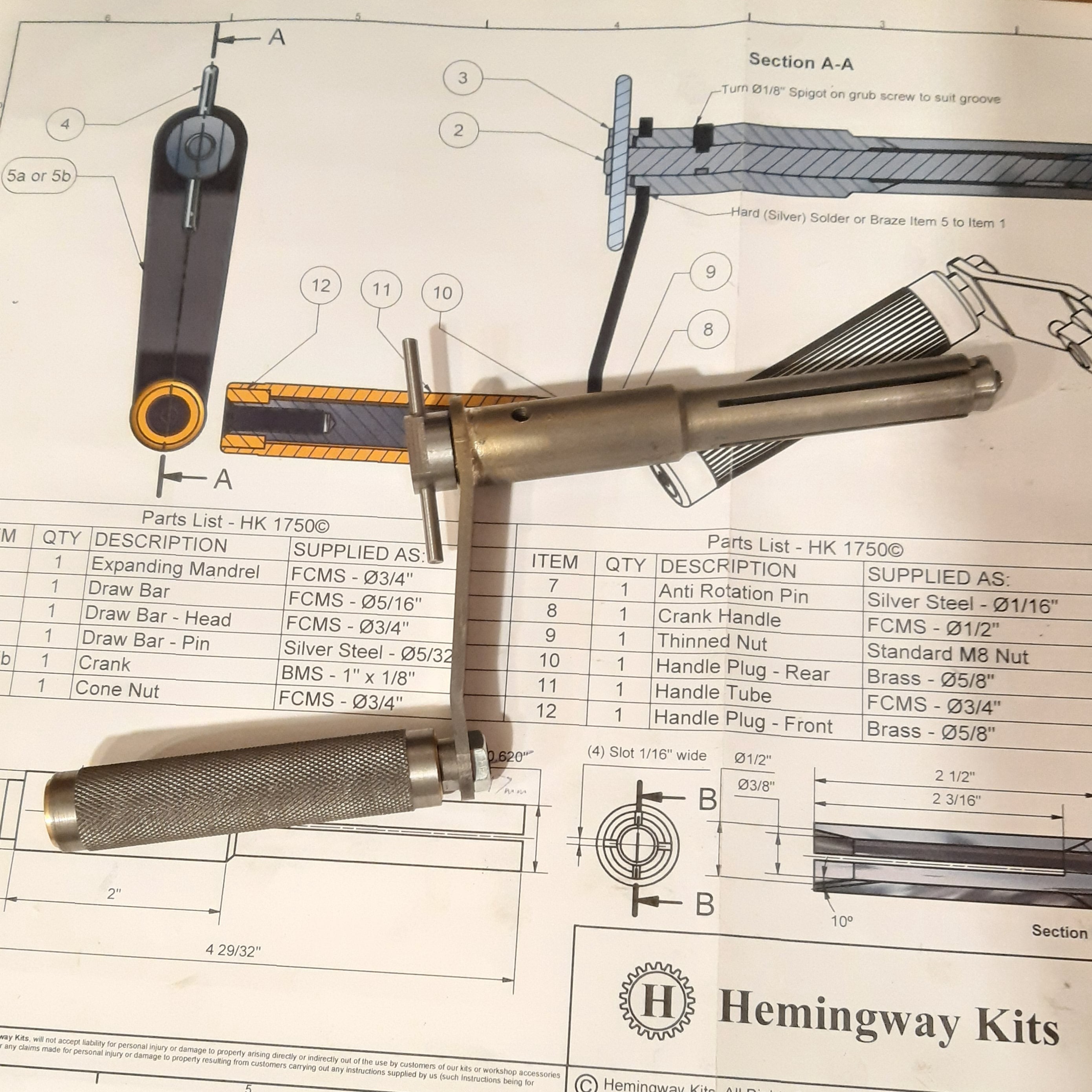
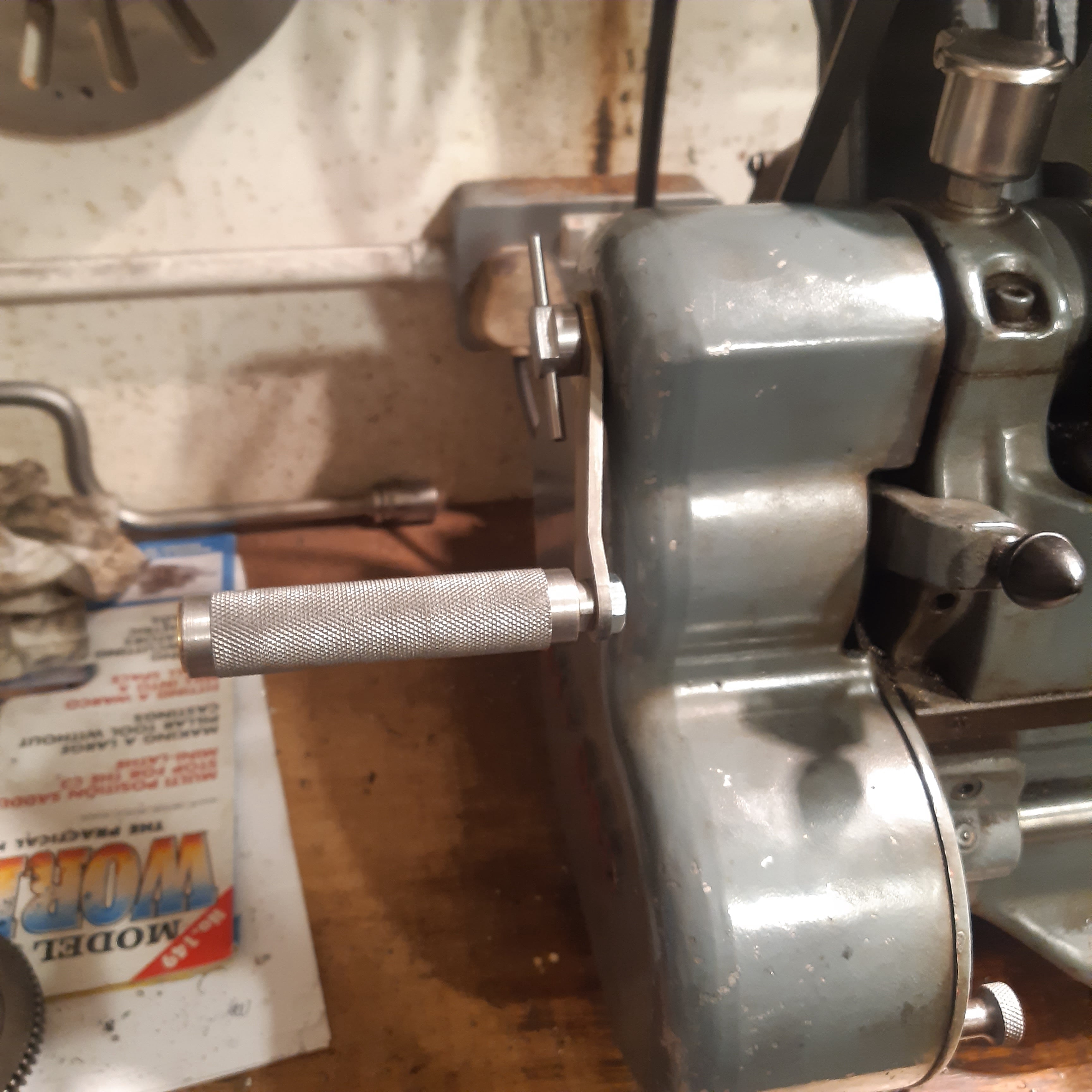
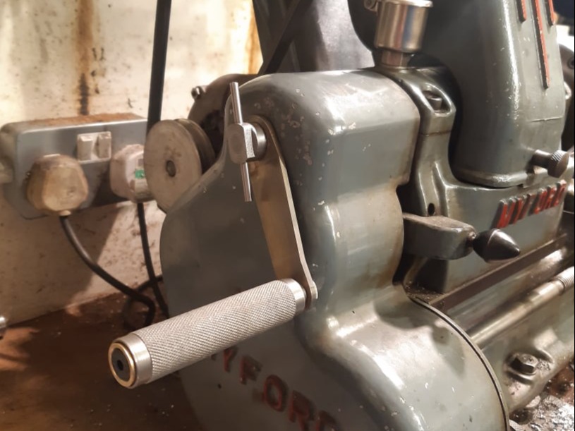
Headstock Handle for the ML7 Lathe

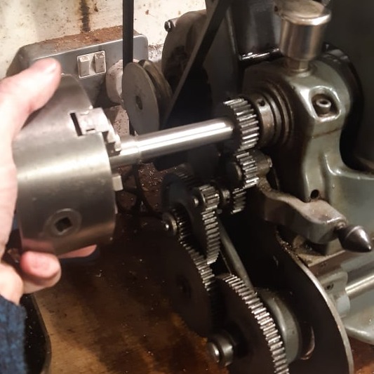
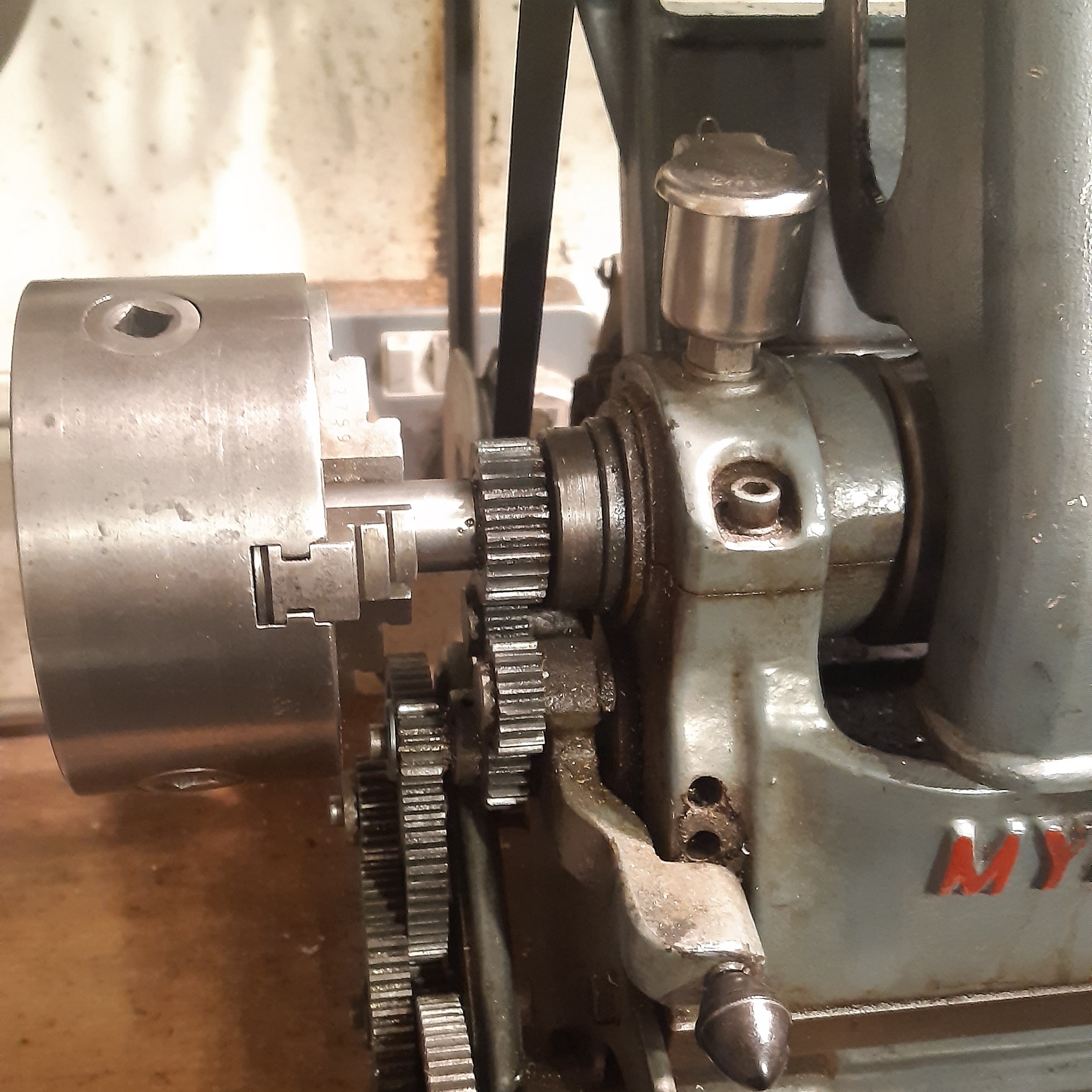
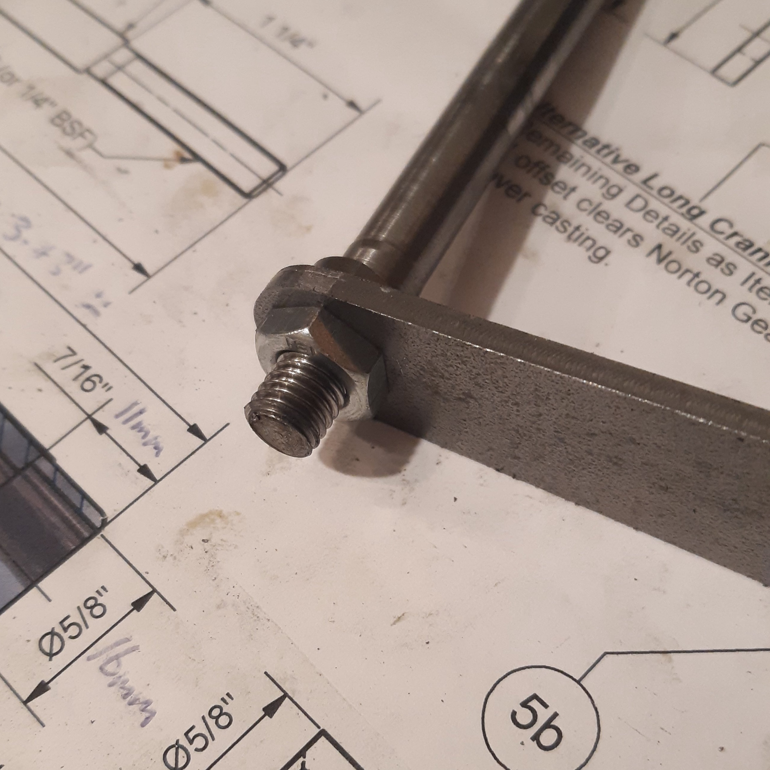
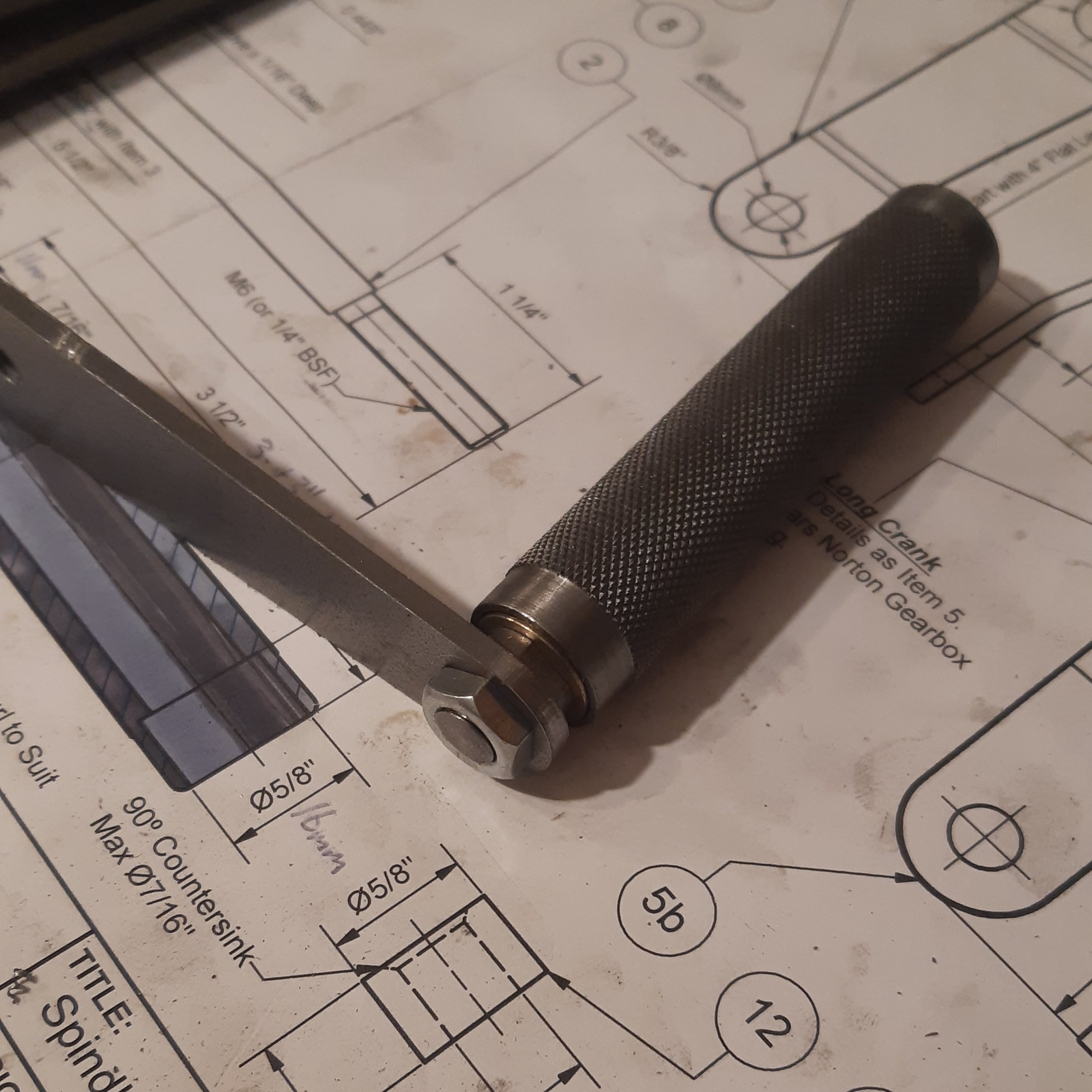
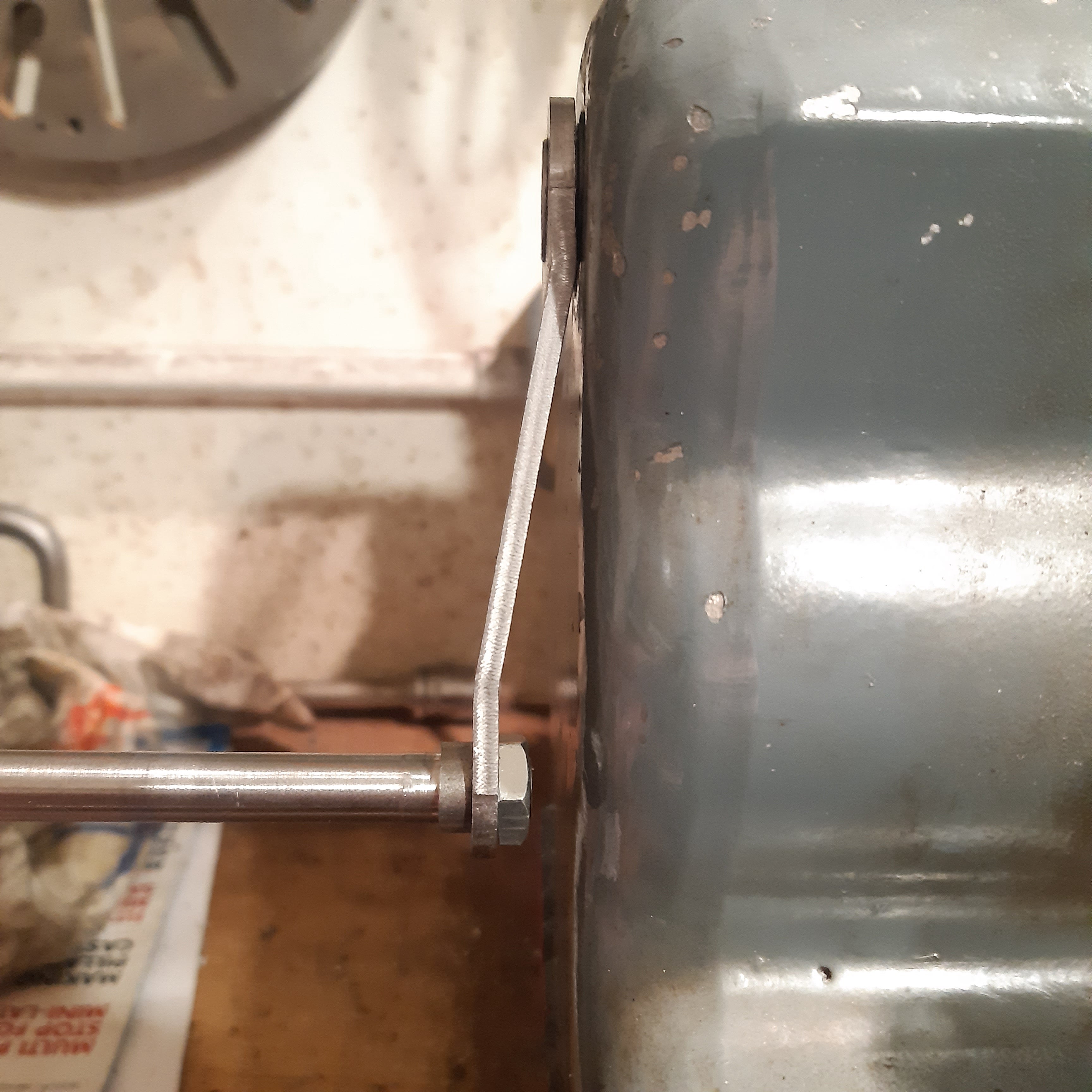
This kit from Hemmingway Kits was designed to fit the headstock of a Myford lathe to enable it to be cranked by hand. This can be useful for slow controlled lathe work or for reversing the headstock by hand during thread cutting.

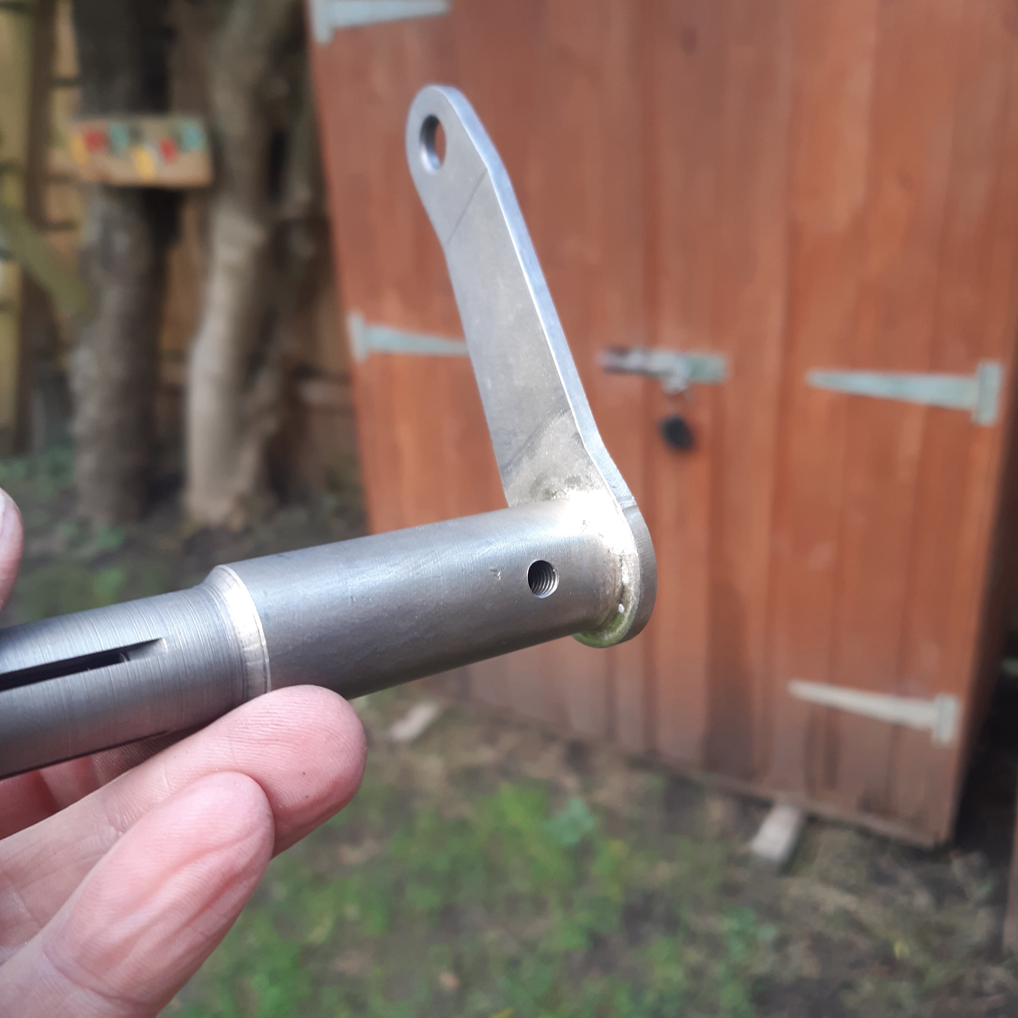
The kit came with two crank length options, one of a 3" throw as per the original design, and another of 5" for more leverage.

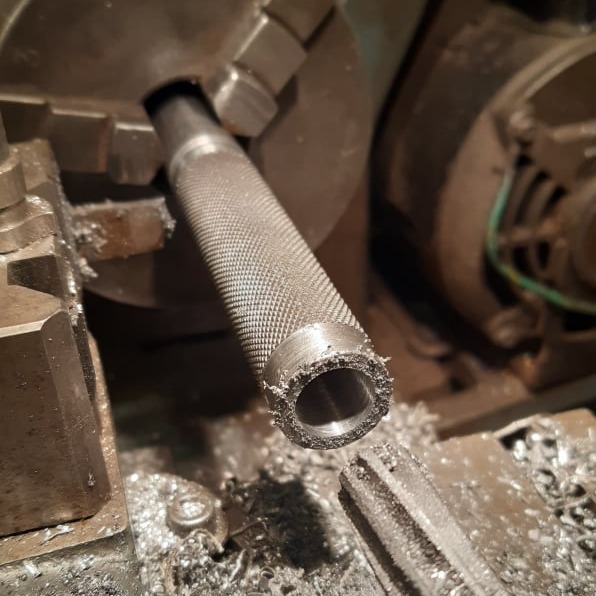
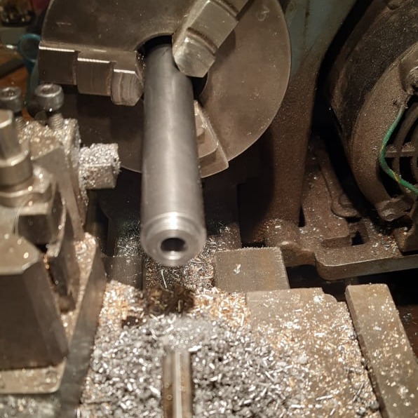
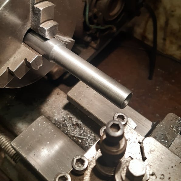
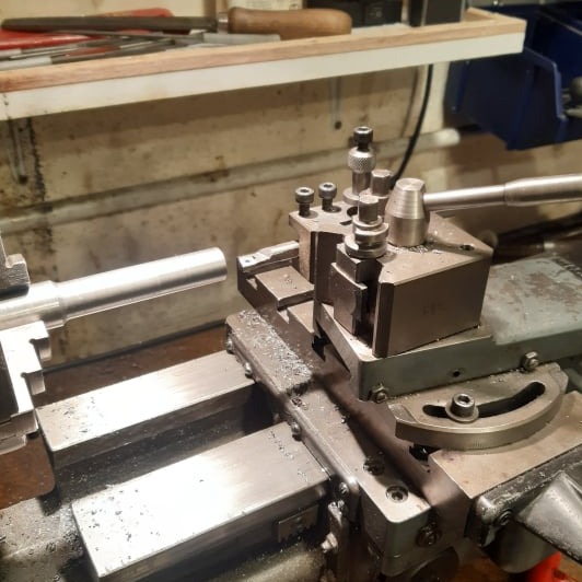
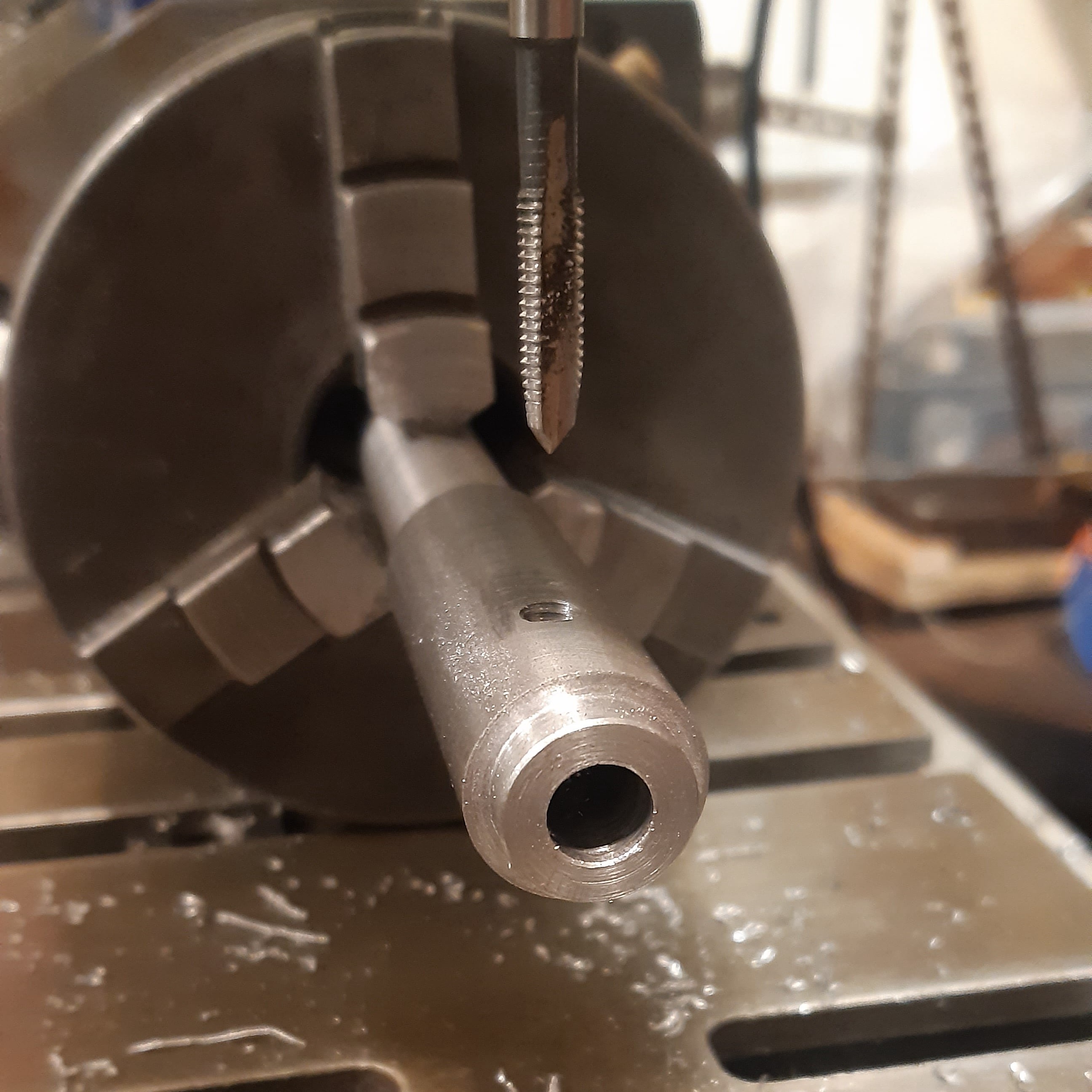
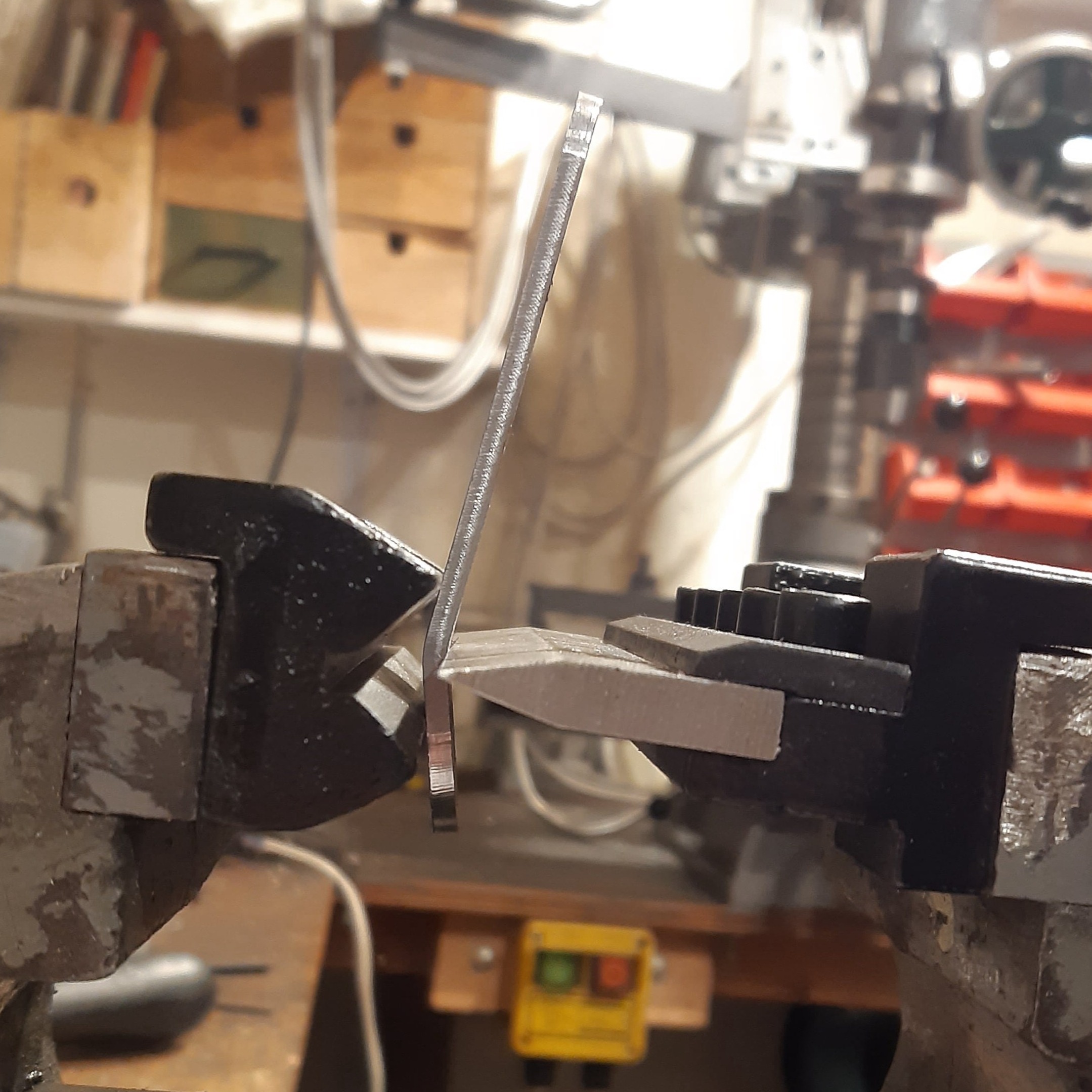
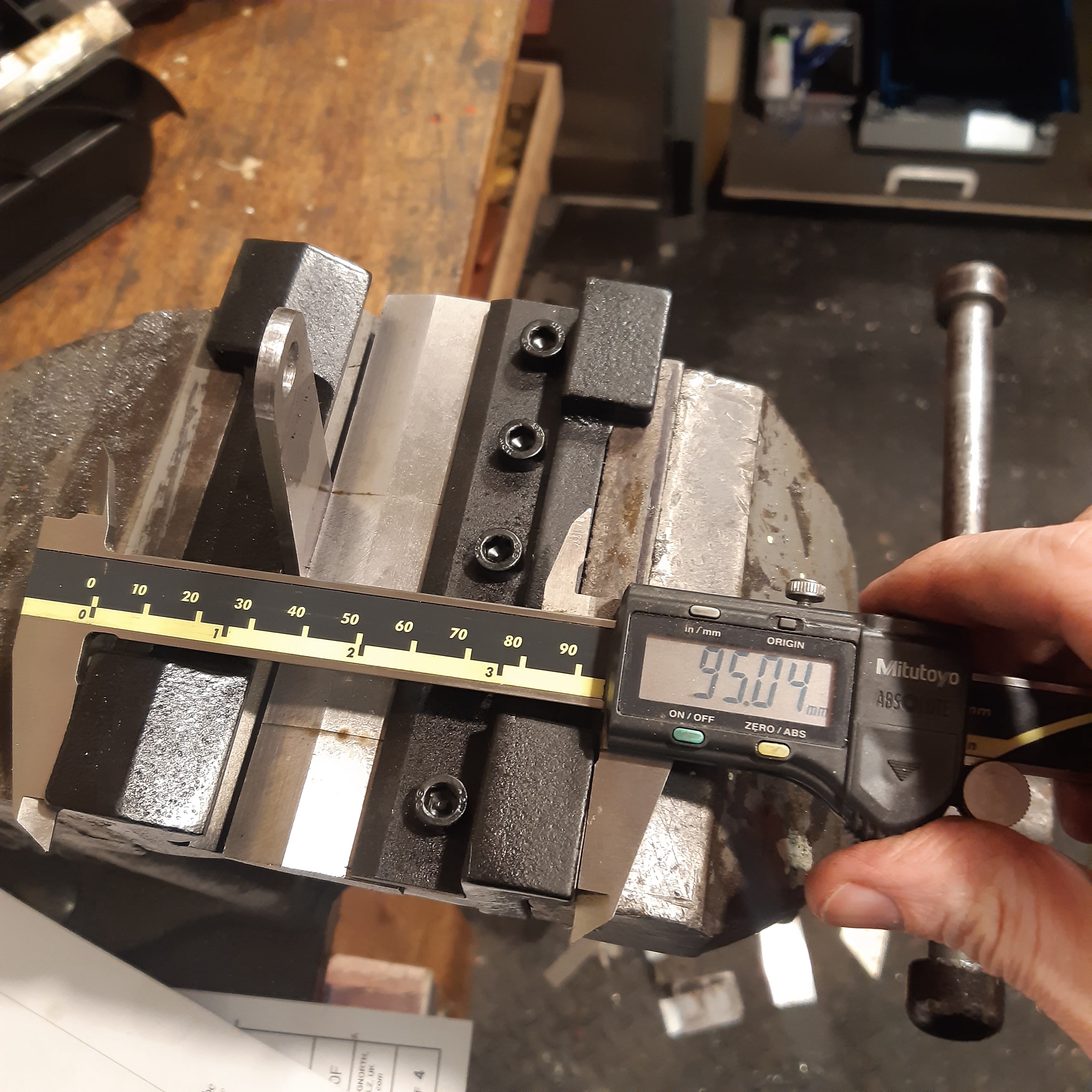
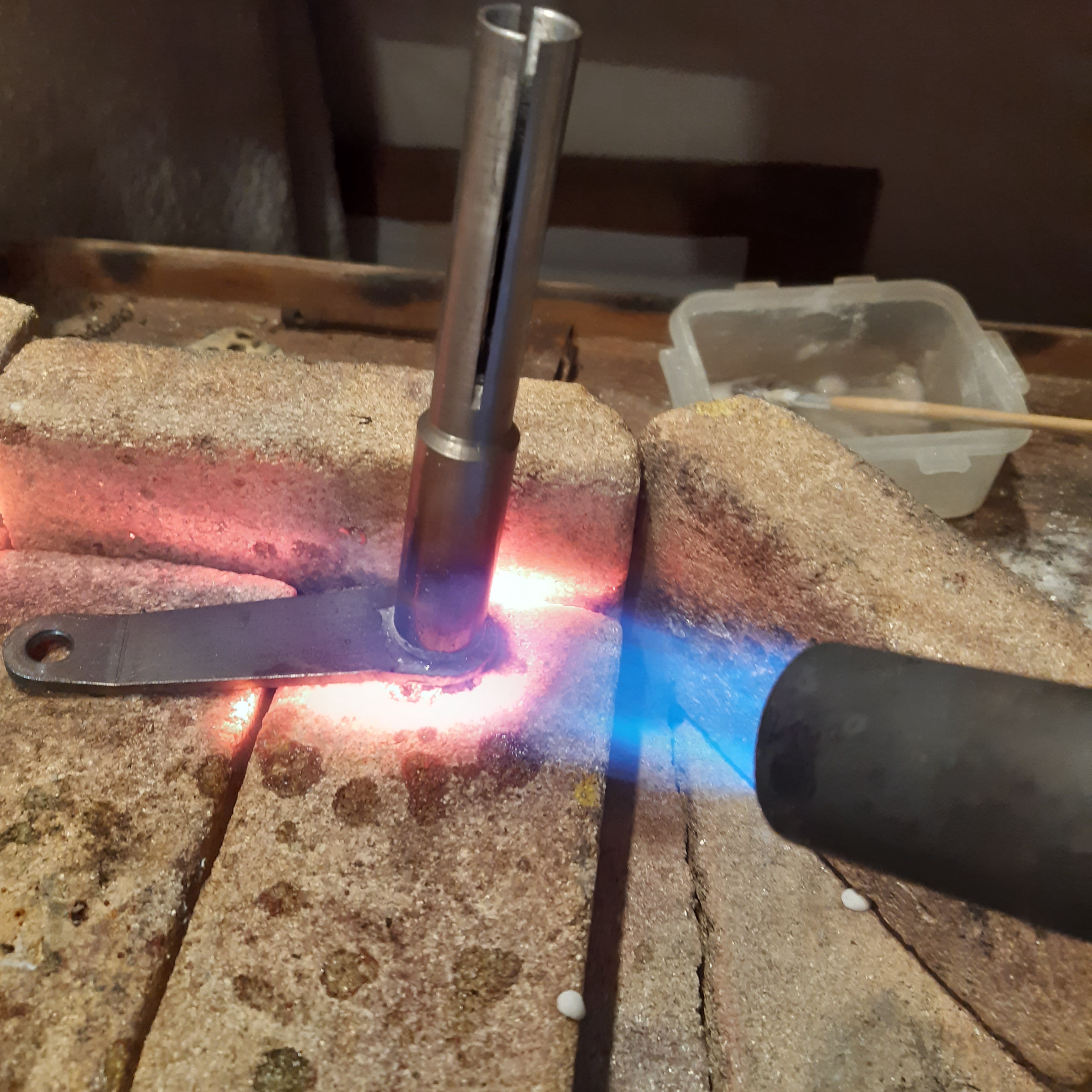
The kit was given as a present and it was machined into the finished article over about 3 days, between Christmas and New Year.

Mobirise Website Builder

The kit from Hemmingway came with some notes, drawings, the materials required and the fixings needed.

Mobirise Website Builder

The handle was knurled using a slow spindle speed and several passes of the tool. Then the centre bore was drilled to size.

Mobirise Website Builder

Both ends of the knurl were cut smooth to give a neat end, and then one end of the handle was counterbored for the brass bearing.

Mobirise Website Builder

Then the part was parted from the bar stock and reversed in the chuck for the counterbore on the other end, The 4-jaw chuck was used to ensure concentricity.

Mobirise Website Builder

The handle pivot was turned between centres, to the required diameter. Followed by the shoulder on the outer end.

Mobirise Website Builder

The part was then reversed in the chuck to create the M8 thread on the other end.
The thread was left over-long at this stage, to make the threading process easier.

Mobirise Website Builder

The milling machine was used to add the flats on the mounting flange to fit an 11mm (7/16") spanner.

Mobirise Website Builder

The bushes for the handle were turned from the brass bar.

Mobirise Website Builder

When assembled, the finished handle should turn freely and easily on the bushes but without rattling.
If the handle is too tight, then one of the bushes can be shortened to get a running fit. If it is too loose, then the pivot can be shortened to reduce end float. 

Mobirise Website Builder

To create the expanding mandrel, a piece of 3/4" BMS was turned to have a shoulder on one end for the crank, and drilled part-way through 5/16" diameter for the drawbar.

Mobirise Website Builder

The other end of the bar was reduced to fit inside the headstock. This was machined using a fine feed and an HSS tool for the best finish possible. The centre was drilled to final size too.

Mobirise Website Builder

The 10° internal taper in the end of the bar was added using a boring bar with the top slide set over by 10°.

Mobirise Website Builder

The chuck was unscrewed to check the fit if the part in the headstock but it was found to be too large.

Mobirise Website Builder

A measurement of the ML7 bore showed it to be 15.19mm, not the 0.620" given in the plans, so the part was reduced to suit.

Mobirise Website Builder

A recheck confirmed the expanding mandrel fitted the bore.

Mobirise Website Builder

The chuck was moved to the rotary table for cross-drilling and tapping of the grub screw thread.

Mobirise Website Builder

The part was reversed in the chuck and the slits cut with a 1/16" slitting saw in the milling machine.

Mobirise Website Builder

The off-cut from the handle was used to create both the drawbar head and the cone nut. After drilling the centre, the chuck was mounted on the milling machine to add the flats.

Mobirise Website Builder

The chuck was moved to the rotary table to orientate the part for cross-drilling for the t-bar.

Mobirise Website Builder

Staying with the rotary table, the part was reverse in the chuck and drilled for the non-rotation pin for the cone nut.

Mobirise Website Builder

Back on the lathe, the thread was added to the cone nut, and the top-slide was set to 10° to turn the taper on the cone.....

Mobirise Website Builder

...then the cone and drawbar head were separated by parting.

Mobirise Website Builder

The cone nut was held on an M6 screw to hand file a radius on the nose.

Mobirise Website Builder

The drawbar head was recessed in the back using a boring tool, and checked for a good fit with the back of the expanding mandrel.

Mobirise Website Builder

The drawbar was reduced at the end to 6mm and cut with an M6 thread to match the cone nut.

Mobirise Website Builder

The drawbar was assembled in the mandrel so the position of the grub screw could be marked. Then the drawbar was recessed in this area with the parting tool.

Mobirise Website Builder

The drawbar was transfer drilled from the handle and reamed to final size.......

Mobirise Website Builder

....before fitting the T-bar pin.

Mobirise Website Builder

The short crank length was chosen and the piece of flat steel marked out and the two holes were drilled 6mm on the drill press.

Mobirise Website Builder

The tapered sides were cut on the milling machine by mounting the part on a piece of scrap aluminum plate using two 6mm holes drilled at the correct height to make the taper.

Mobirise Website Builder

The radii were filed by hand and then trimmed using the same plate. Light cuts were used whilst rotating the part by hand BUT avoiding climb milling at any point which could lead to sudden failure.

Mobirise Website Builder

The standard M8 nut was thinned on the lathe. The nose of the tailstock chuck was used to set the nut square in the chuck before machining.

Mobirise Website Builder

The small hole in the crank was drilled to 8mm and the handle spindle was assembled with the thin nut, so that the thread could be machined to length.

Mobirise Website Builder

This photo shows the handle mounted on the crank with the thin nut and shortened thread.

Mobirise Website Builder

A press brake pair of jaws were used in the vice to fold the thick metal handle neatly.

Mobirise Website Builder

The width of the jaws was measured and copied to the second fold to get the same angle in both cases.

Mobirise Website Builder

The formed crank was checked for clearance against the change wheel cover on the lathe.

Mobirise Website Builder

Then the crank was silver-soldered to the expanding mandrel......

Mobirise Website Builder

....and cleaned up using citric acid in hot water.

Mobirise Website Builder

Finally, the M5 retaining grub screw had to be shortened to fit flush with the mandrel body.

Mobirise Website Builder

The finished handle on the lathe.

AI Website Creator