Mobirise Website Builder

CAD and Model Engineering

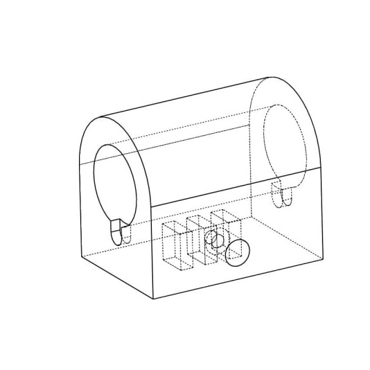
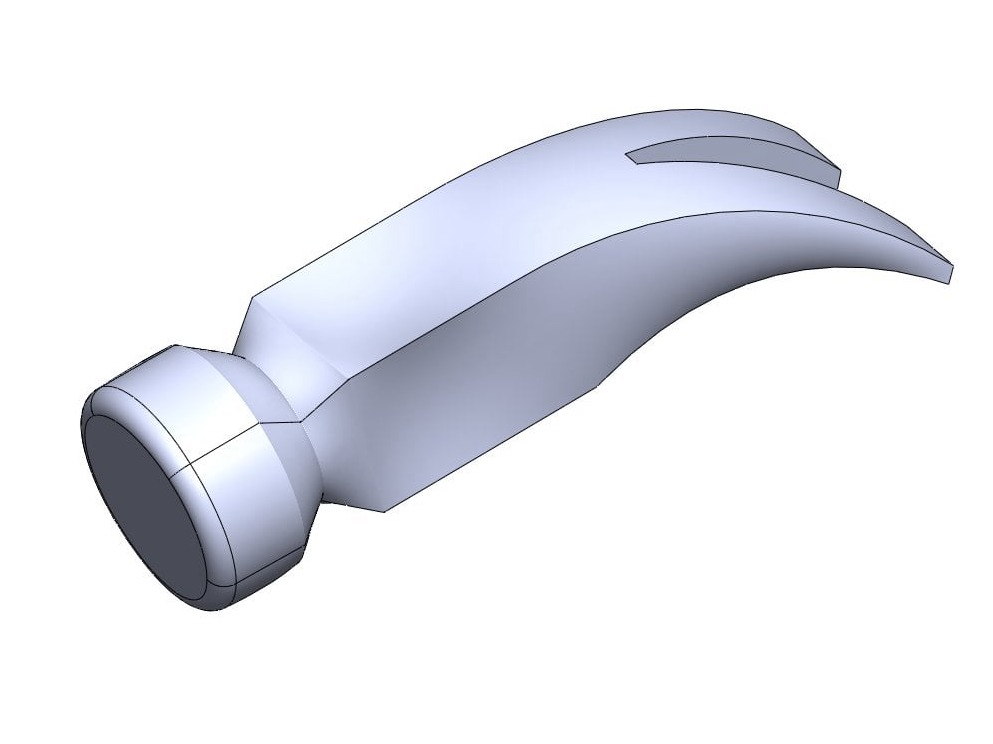
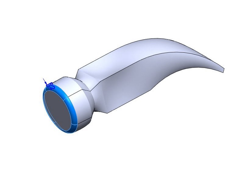
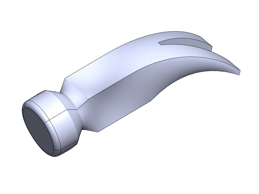
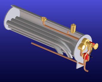
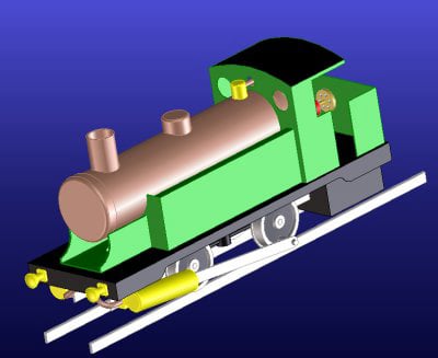
This page talks about Computer Aided Design (CAD) and how it can be useful for model engineers and hobbyists to design parts for projects. As well as part design, CAD can be used to check the fit of parts, to check for clashes in moving assemblies, to export 2D drawings for manufacture and to create files suitable for 3D printing.

CAD softwares are constantly evolving and new options appear, but at the time of writing this page (2023) some free options are; Creo elements express, Onshape, Sketchup, freeCAD, Fusion 360, Solid Egde and NanoCAD.

CAD software can be intimidating due to a high number of menus and options but most software works in a similar way. There are typically some 2D sketch tools to create profiles and then some 3D operations to create 3D parts from your sketch. Once you have the initial body created you can continue with more sketching and 3D operations to add details to your part, or there are a number of 3D functions such as tapers, ribs and chamfers that can be applied direct to the 3D model. This page explains what some of the more common functions are using some worked examples. The software commands are shown in bold italic text.

Basic Commands

Mobirise Website Builder

This 2D sketch shows a circle with a 12mm diameter.

Mobirise Website Builder

If we extrude the circle by 20mm, we get a cylinder. This could be the piston for a model steam engine.

Mobirise Website Builder

A 10mm circle can be sketched on one end face.

Mobirise Website Builder

This time, an extruded cut can be used to a depth of 19mm. This gives us a part which could be a cylinder of a small steam engine.

Mobirise Website Builder

We can take the same starting sketch and add a vertical construction line, 25mm away.

Mobirise Website Builder

Then the rotate or revolve function is available and we can produce a doughnut shape; an O-ring or a tyre perhaps.

Mobirise Website Builder

The revolve function doesn't have to be 360°. Here the same profile has been rotated by 225° to create the basis of a hook.

Mobirise Website Builder

The sketch doesn't have to be a regular shape either. Here a "U" is being extruded to create a channel section.

Mobirise Website Builder

And this image shows a circle sketched on one side of the channel.

Mobirise Website Builder

An extruded cut can then cut the sketched profile from the part to create a small bracket.

Mobirise Website Builder

Fillets are 3D radii that can be added along any edge. Here they have been added to make the part look like sheet metal.

Mobirise Website Builder

And this image shows two slots sketched on the base with an extruded cut applied, for mounting holes.

Mobirise Website Builder

A lot can be achieved just using the extrude, rotate and cut commands, because actually the majority of machined parts in the home workshop, are cylindrical or rectangular.

The toy locomotive shown on the left was created just using cylinders, rectangles and sketched cuts. The software used fort his model is called Creo Elements Direct, and can be downloaded from :
https://www.ptc.com/en/products/creo/elements-direct/modeling-express
The software is free to download and use, but is limited to 60 parts in an assembly. Larger models would, therefore, have to be broken down into sub-assemblies.

The process to create a couple of the parts  is shown below.

Mobirise Website Builder

Something like the buffers can be created starting with a half profile sketch like the one shown above....

Mobirise Website Builder

...followed by the revolve function about the horizontal line.

Mobirise Website Builder

An extruded square with rounded corners sketched on the back face could make a mounting plate, with some holes cut for rivets.

Mobirise Website Builder

Add some face colour to help you visualise the design.

Mobirise Website Builder

The cab can be made by extruding the correct profile to the required depth.

Mobirise Website Builder

The shell command is a powerful way to hollow out a shape. Just define the wall thickness and select any faces to remove.

Mobirise Website Builder

An extruded cut on the front face could be used to create windows and a cut-out for the boiler.

Mobirise Website Builder

Another extruded cut from a  "P" shaped sketch on the cab side, will create the side profile. Add colours if you like.

Mobirise Website Builder

Sketch planes

So far all the sketches have been placed on the face of a part. If a sketch is needed somewhere else, a custom sketch plane can be created. A sketch plane is like a piece of paper which the user can place anywhere in the workspace to drawn on. Some CAD software will give the user one sketch plane to start with, others will give X, Y and Z sketch planes as shown here.
However, if a sketch plane in a specific location or at a specific angle is needed, the user can define one to allow the sketch and subsequent 3D operation to have the desired affect. In the example below there is a need to model the angled hole in a cylinder casting to connect the valve to the steam inlet of the cylinder.

Mobirise Website Builder

Here is the cylinder casting made from an extruded body with various extruded cut profiles where needed.

Mobirise Website Builder

The part requires a hole at 20° to the end face. This can be done by setting up a sketch plane at 20° to one end face.

Mobirise Website Builder

Now a circle can be sketched on the plane and the extruded cut operation will make a hole at the required angle.

Mobirise Website Builder

With the extruded cut operation set to the correct depth, a cross-section view can be used to show the angled hole.

Advanced Functions

Many CAD softwares will offer some more advanced functions such as lofts, sweeps, helical curves and the ability to create 3D sketches. Below is some information on how these commands work.

A sweep is similar to an extruded part, but in this case, the path of the extrusion is not linear, nor a circle, but a profile sketched by the user. For example, drawing a handrail for a locomotive cab.
Mobirise Website Builder

For this part we could start with a sketch of a circle, the diameter of the grabrail. 2mm in this case.

Mobirise Website Builder

Then a second sketch describing the path we want for the profile is needed. This sketch should start from the centre of the circle as shown.

Mobirise Website Builder

Then the circle can be "swept" along the sketched profile using the sweep command.

Mobirise Website Builder

Some circular extrusions could be added as mounting plates.

A loft adds another variable to the 3D operation. Like the sweep command you are moving a cross-section along a path, but this time the cross-section can vary too. In this case, the user will need to define more than one cross-sectional sketch, as well as the path for the loft and sometimes some guide curves to tell the software which vertices to connect.
Mobirise Website Builder

Let's say we want to model a hammer head which is circular at one end, narrowing to a square where it joins the handle and then tapering to a rectangle along a curve for the claw.

Mobirise Website Builder

A number of sketch planes will need to be set up in the correct place, each one with a profile sketched for that section of the hammer.

Mobirise Website Builder

A guide curve may be needed to help the software understand which vertices should be connected. This gives the option to twist a part throughout the loft if desired.

Mobirise Website Builder

The loft command will request the profiles to be used and any guide curves for the form.

Mobirise Website Builder

A fillet can be added to the hammer head

Mobirise Website Builder

And a "V" shape sketch on the horizontal plane can be used with an extruded cut to create the claw.

Mobirise Website Builder

Assemblies 

Finally, we should mention assemblies. When you have more than one part drawn up, you may want to put them together in an assembly to check the fit and alignment of features.
Most CAD software will have another environment where you can assemble parts. Relations or mates are used to define how parts go together. A piston should be concentric in a bore for example. You can also align faces and axis, make parts perpendicular, or place them a fixed distance or angle from each other.
Once an assembly has been created it is often possible to check for clashes and also subtract one part from another to create a matched socket from a plug for example.

Drag & Drop Website Builder