Mobirise Website Builder

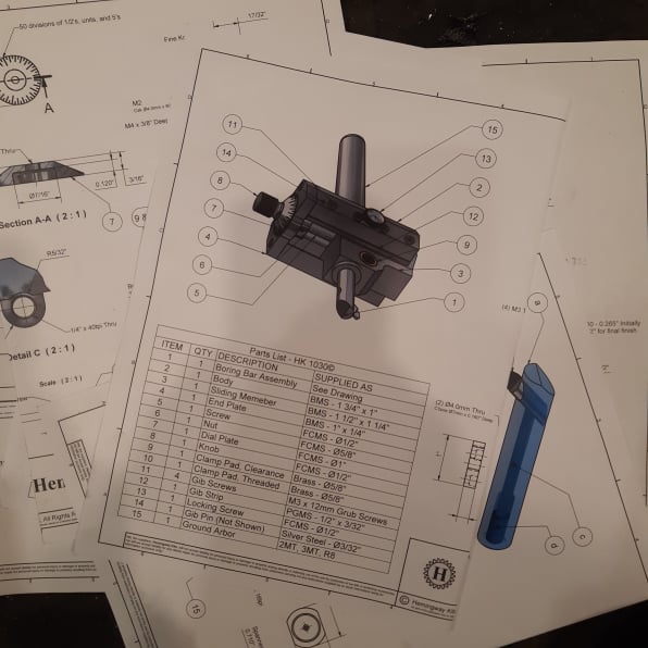
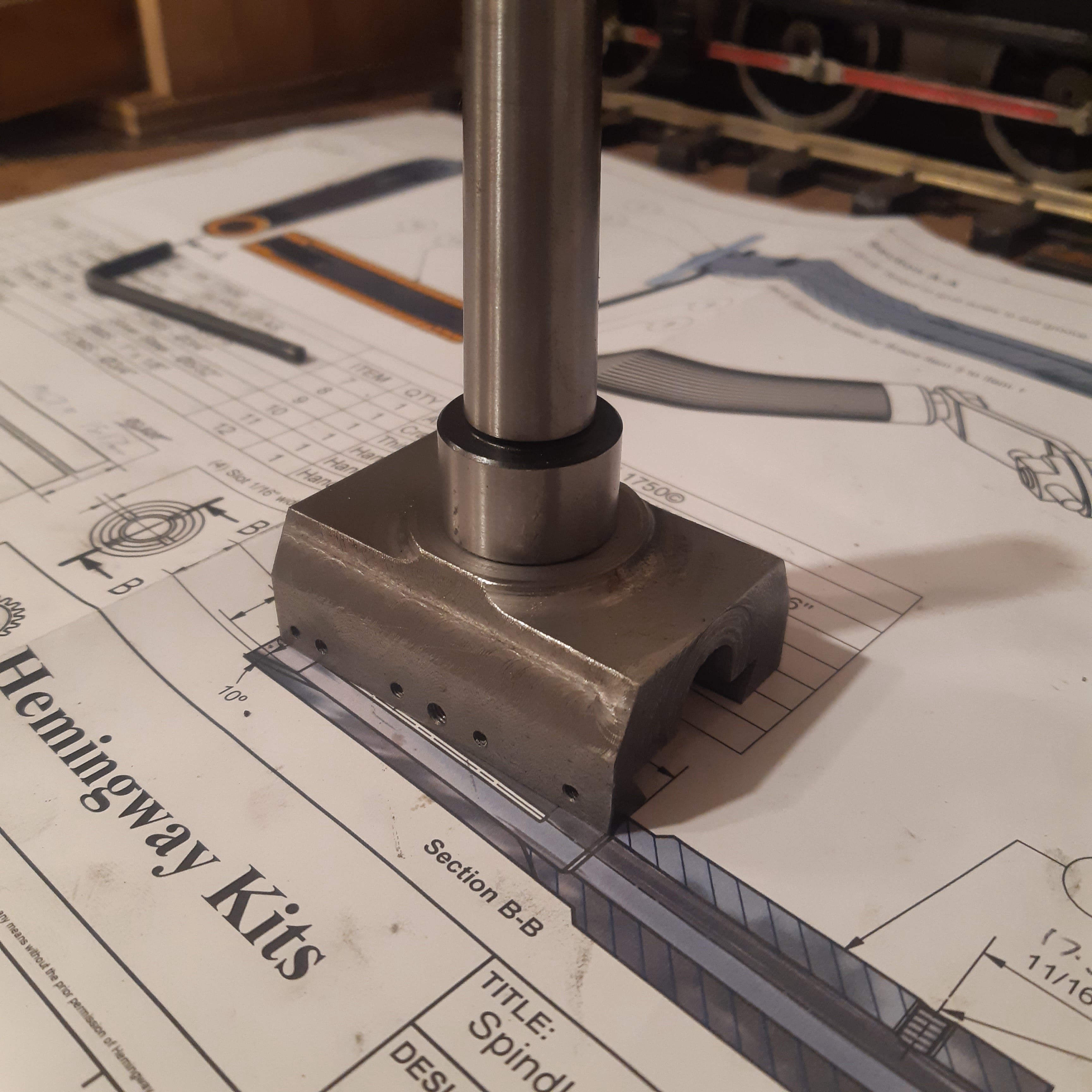
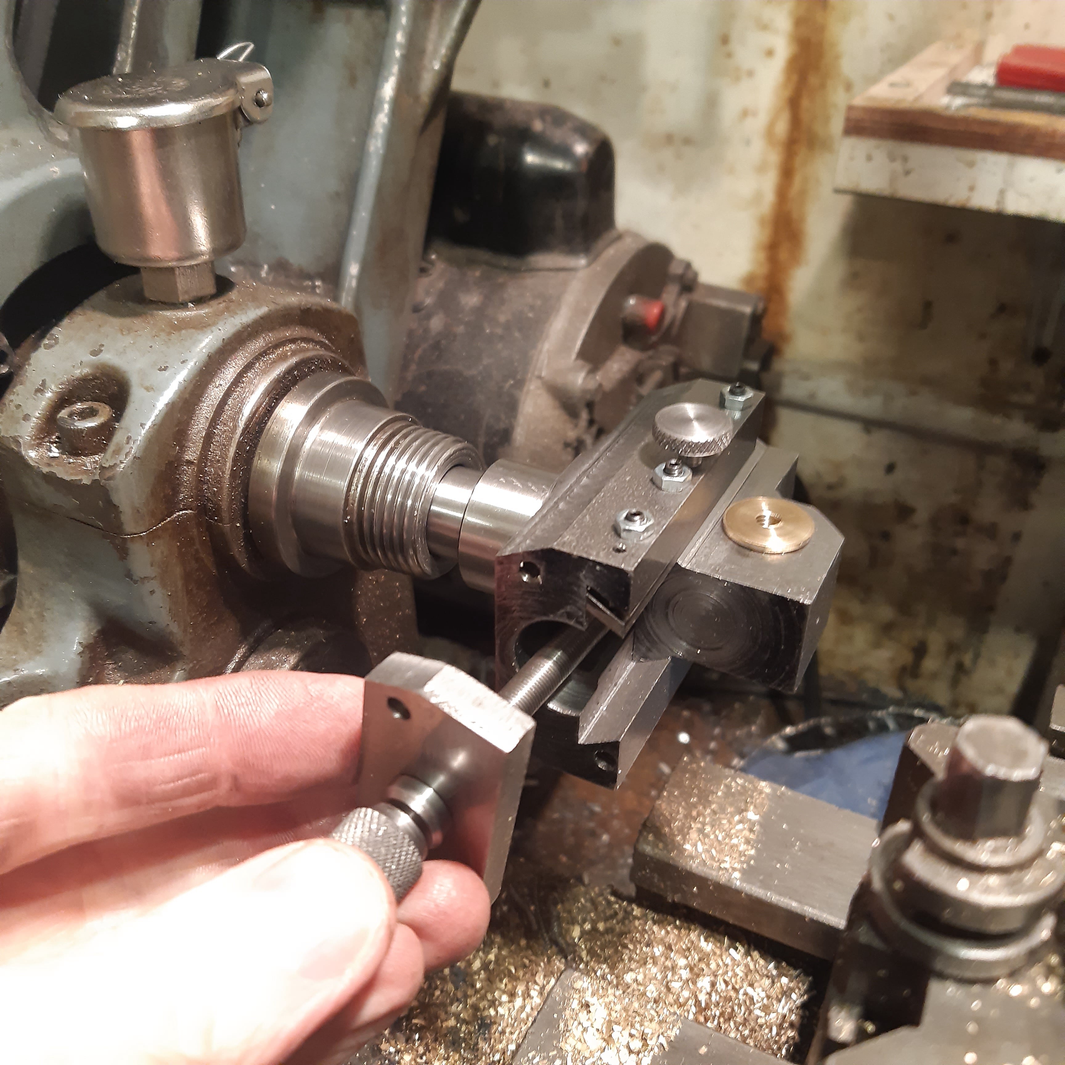
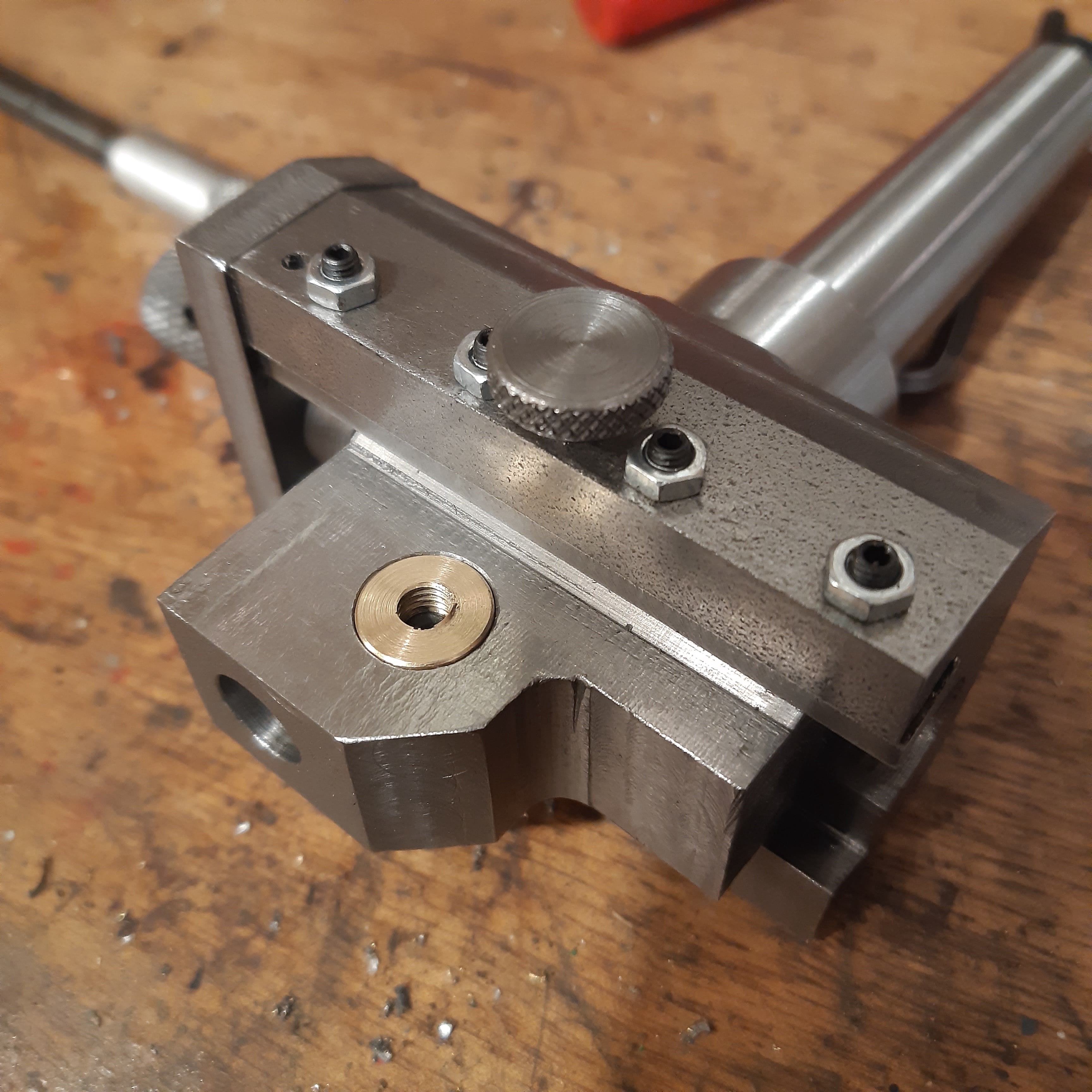
Making a boring head

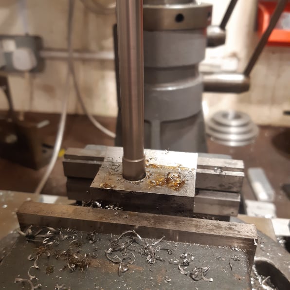
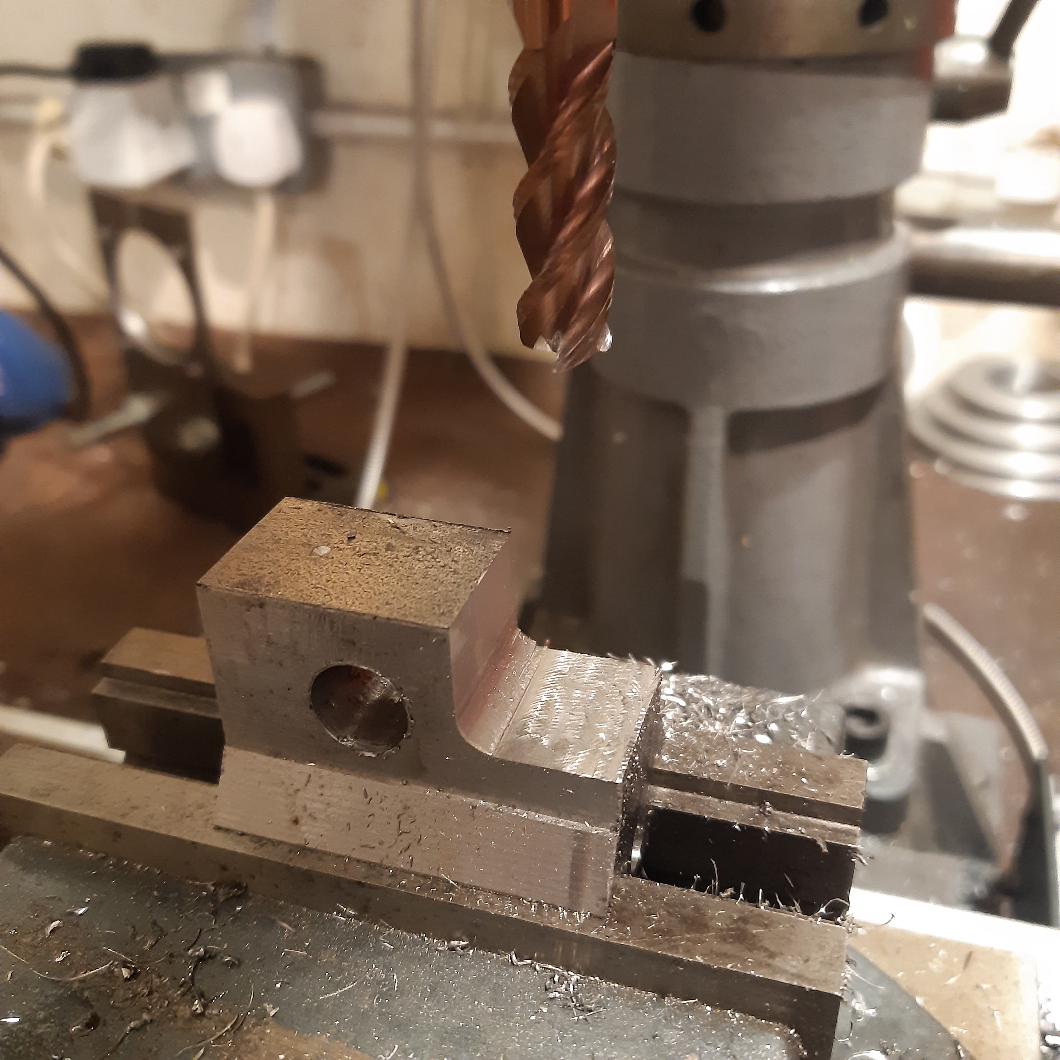
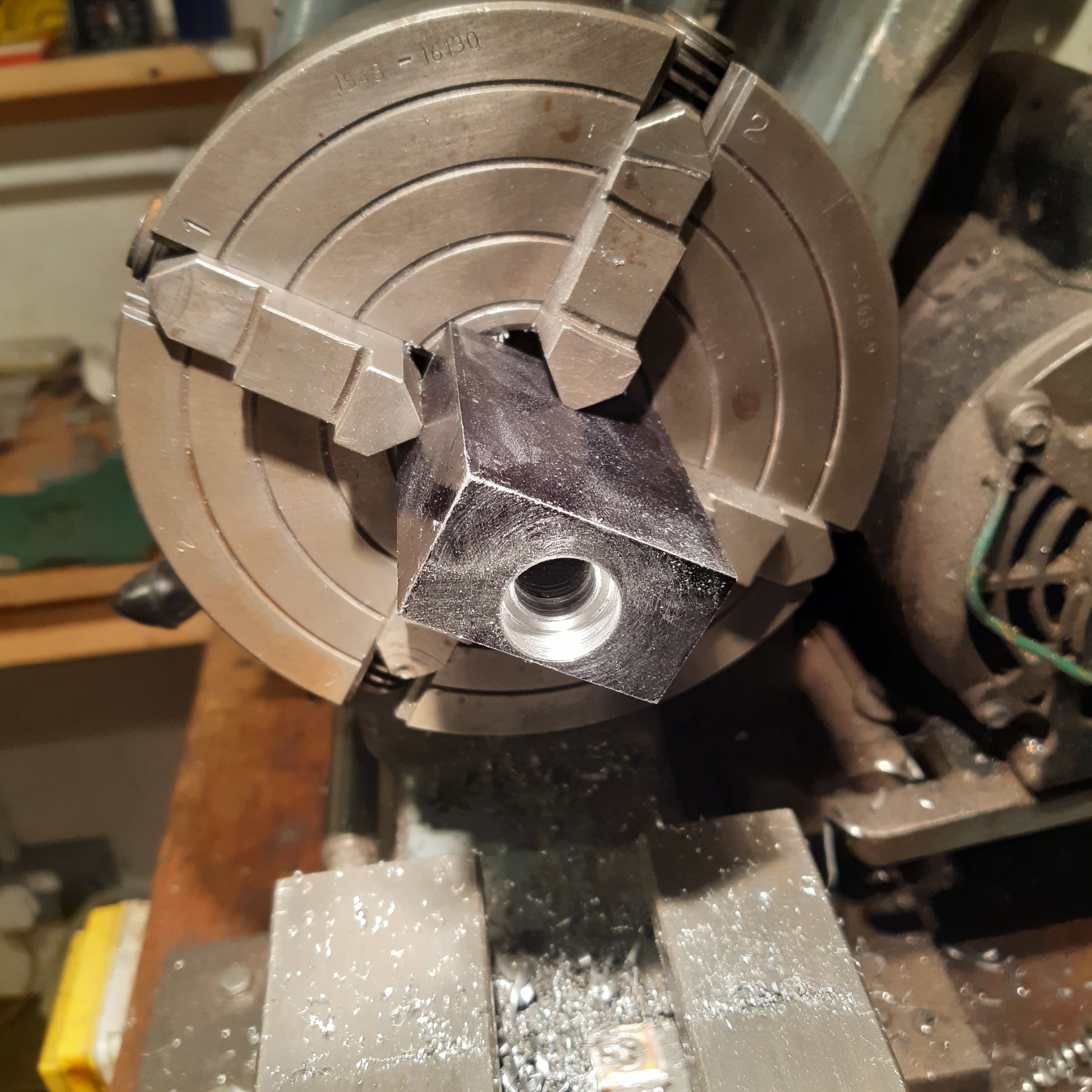
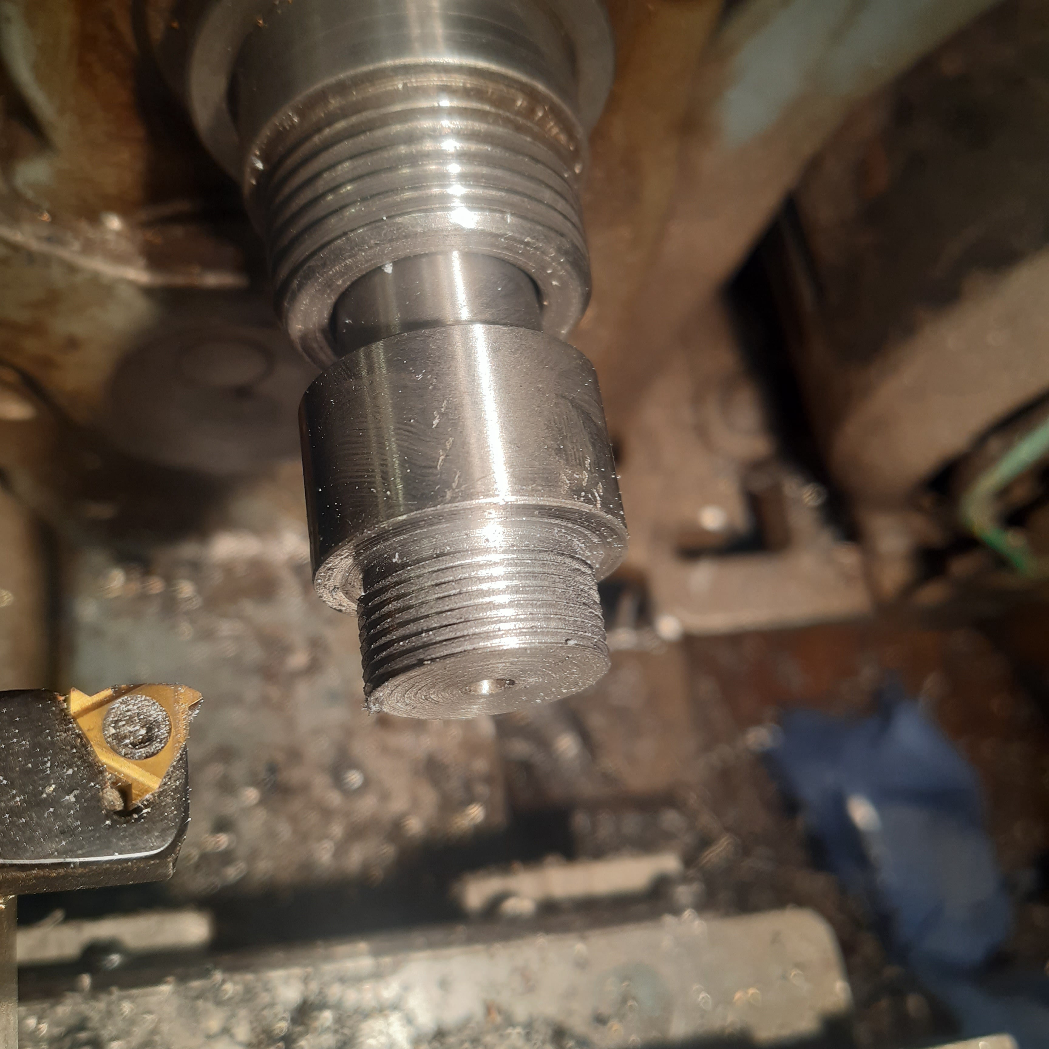
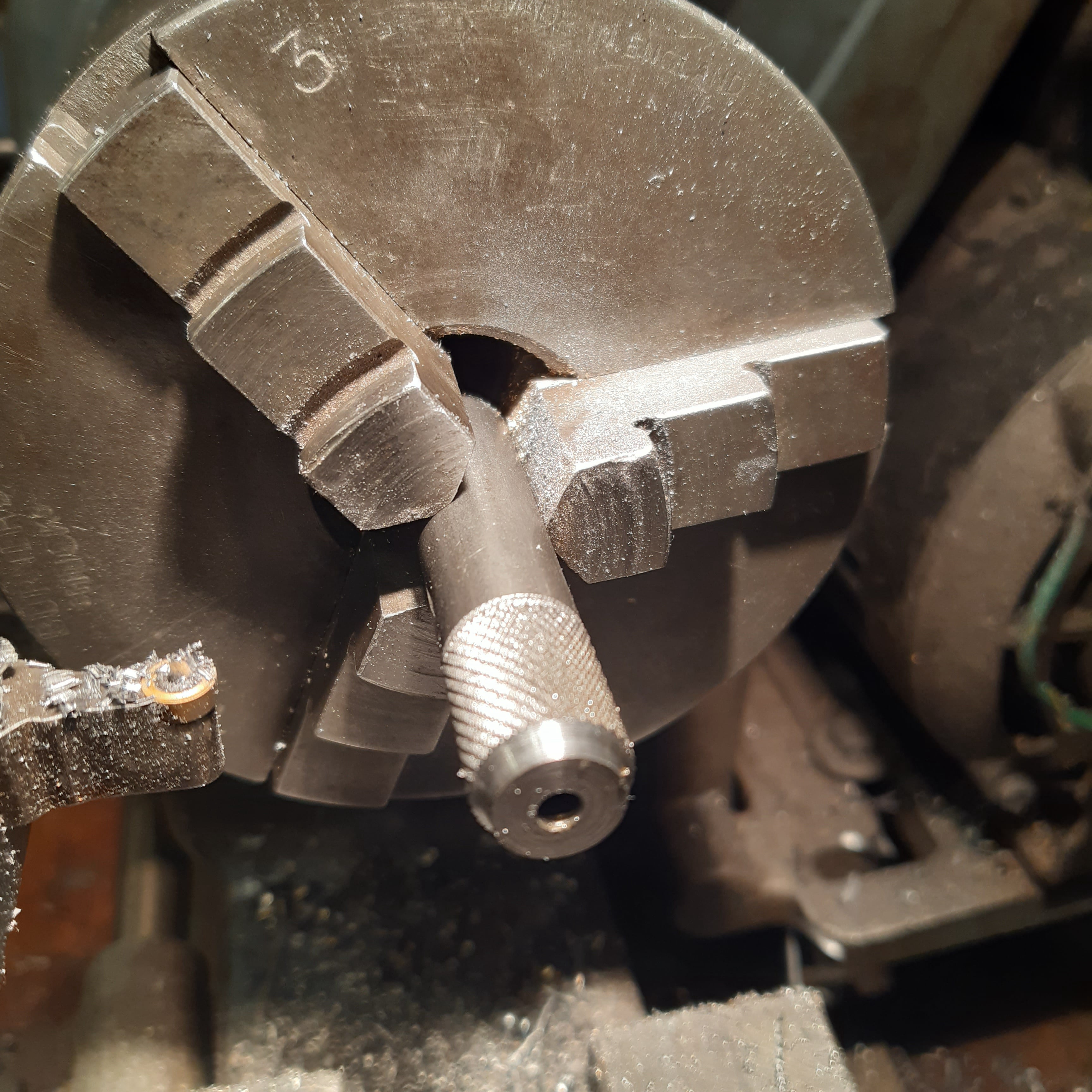
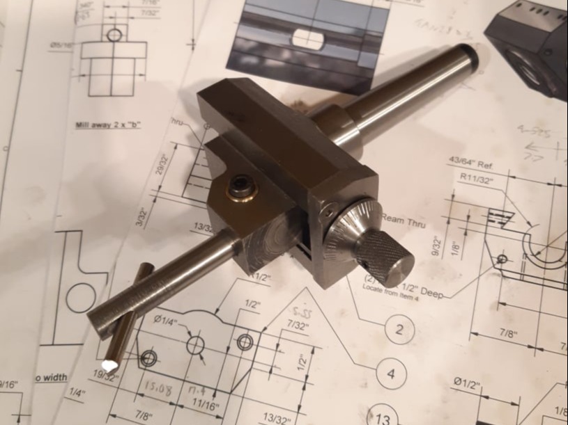
Another kit from Hemmingway Kits. This one was to make a boring head for the milling machine. A kit was purchased with an MT2 arbor.
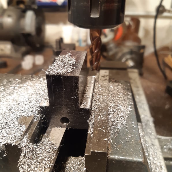
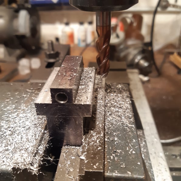
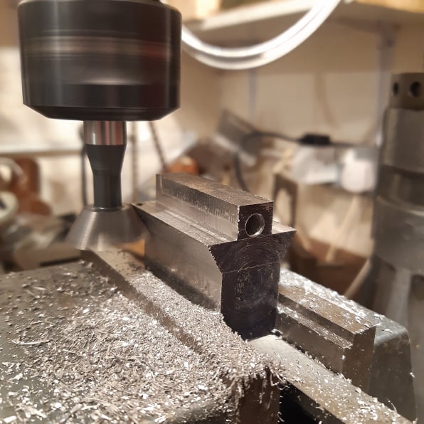
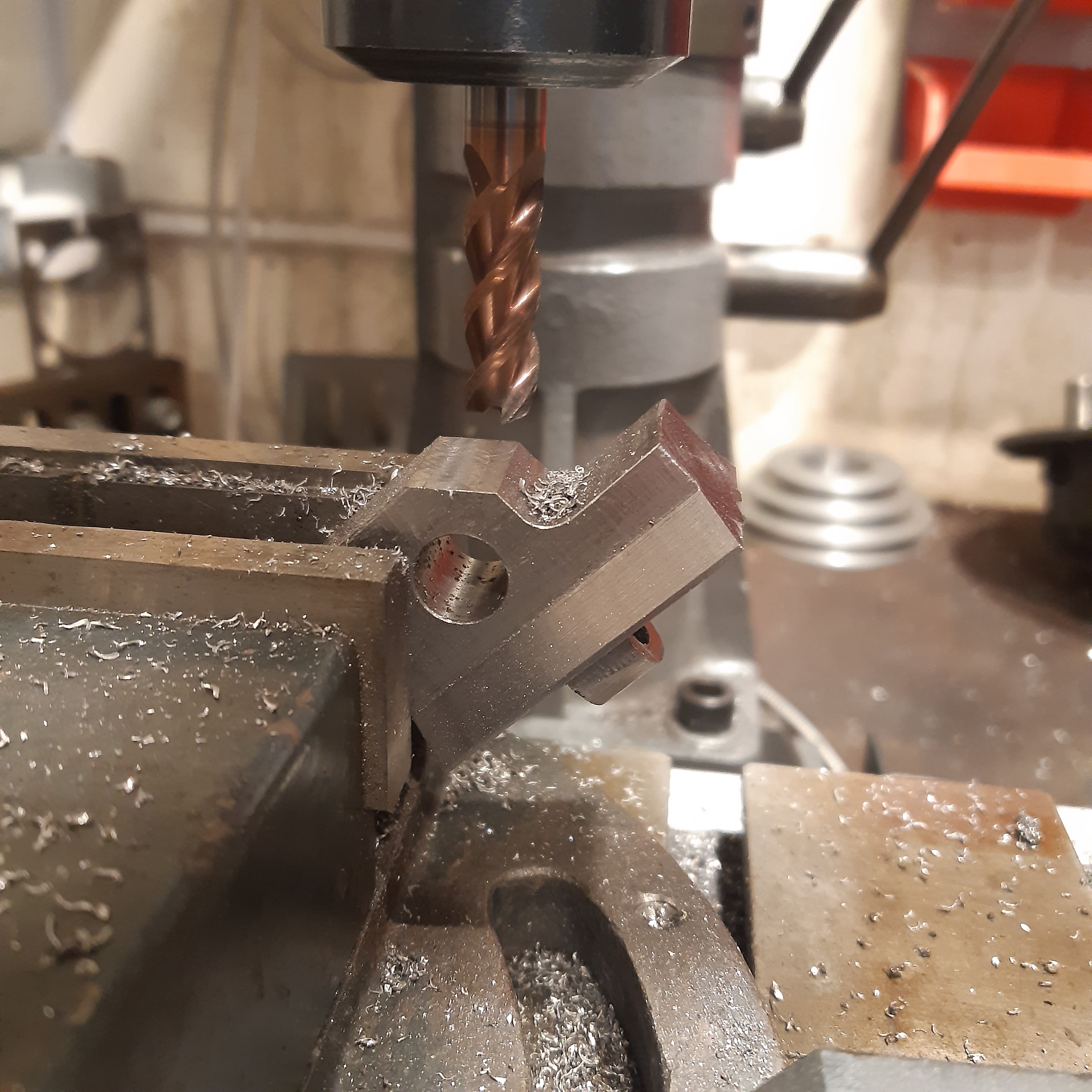
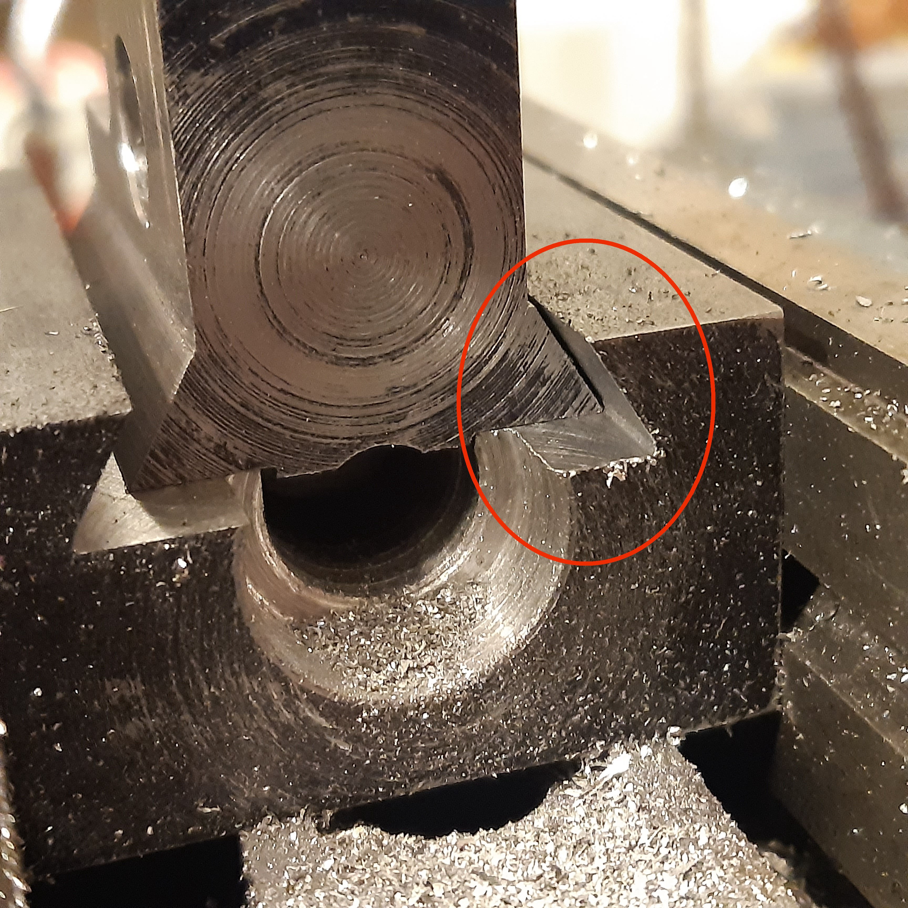
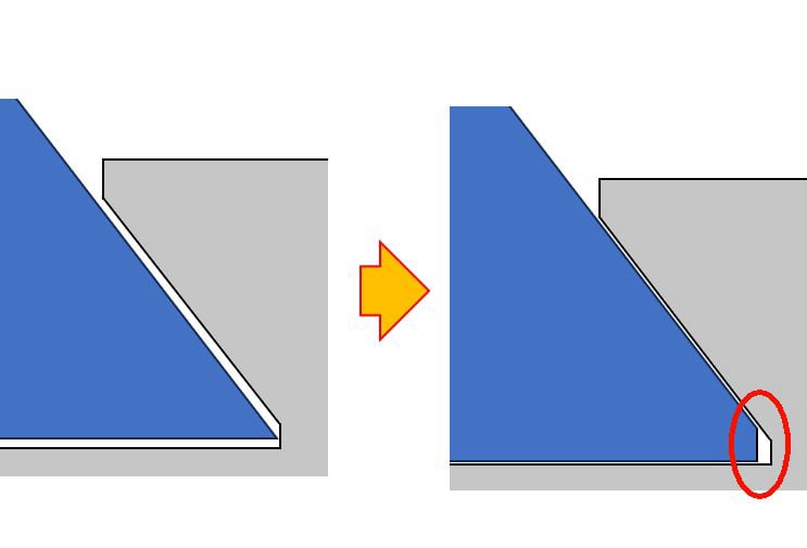
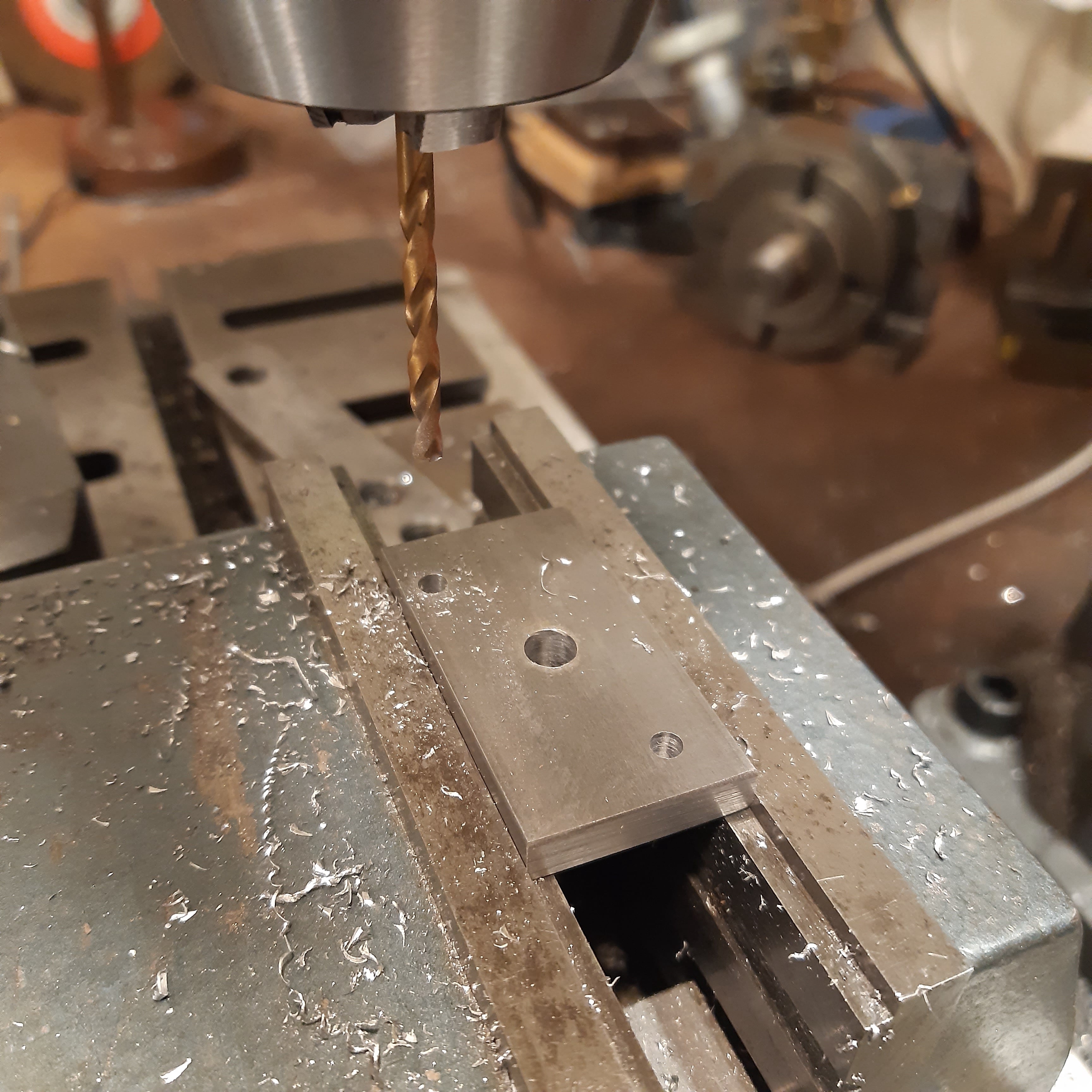
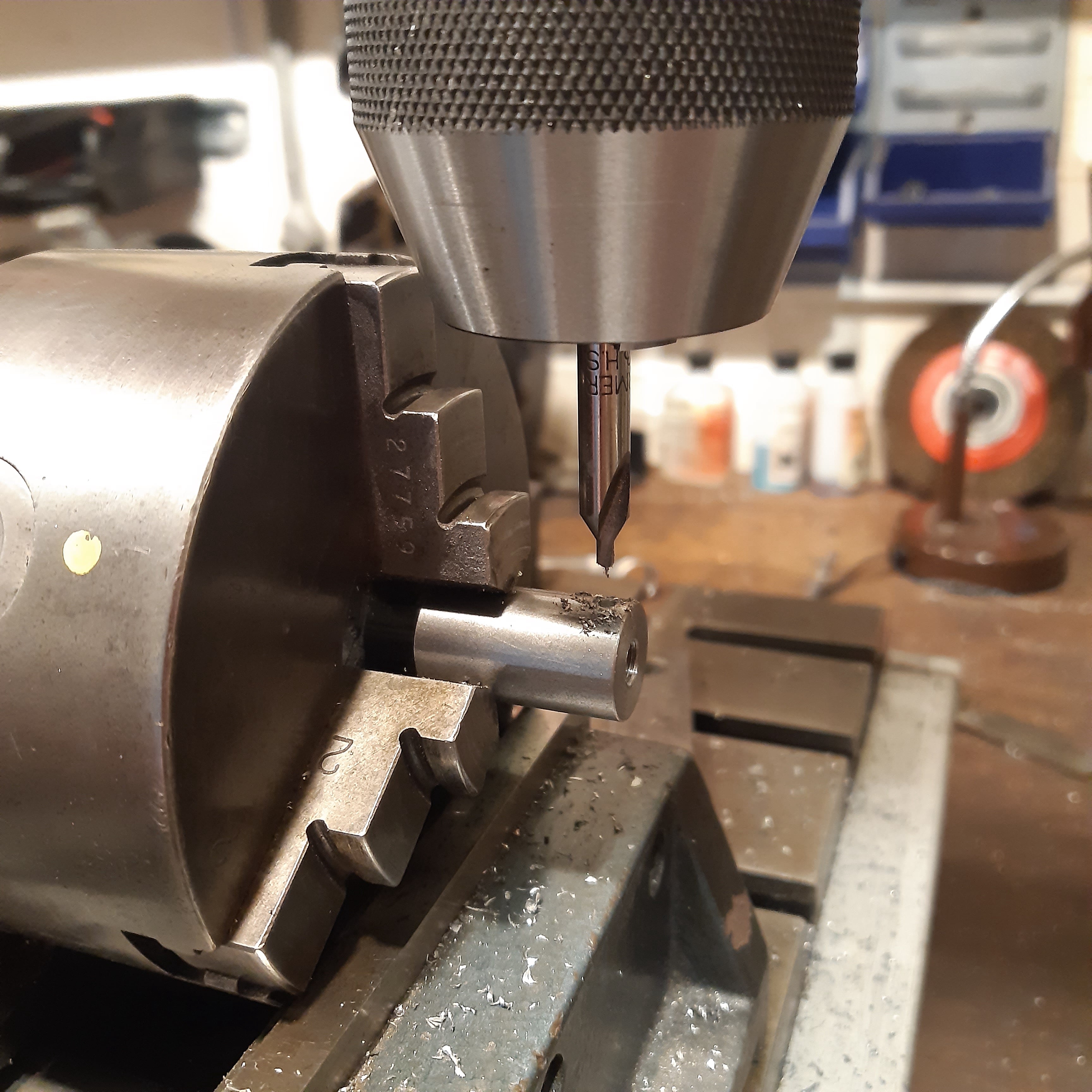
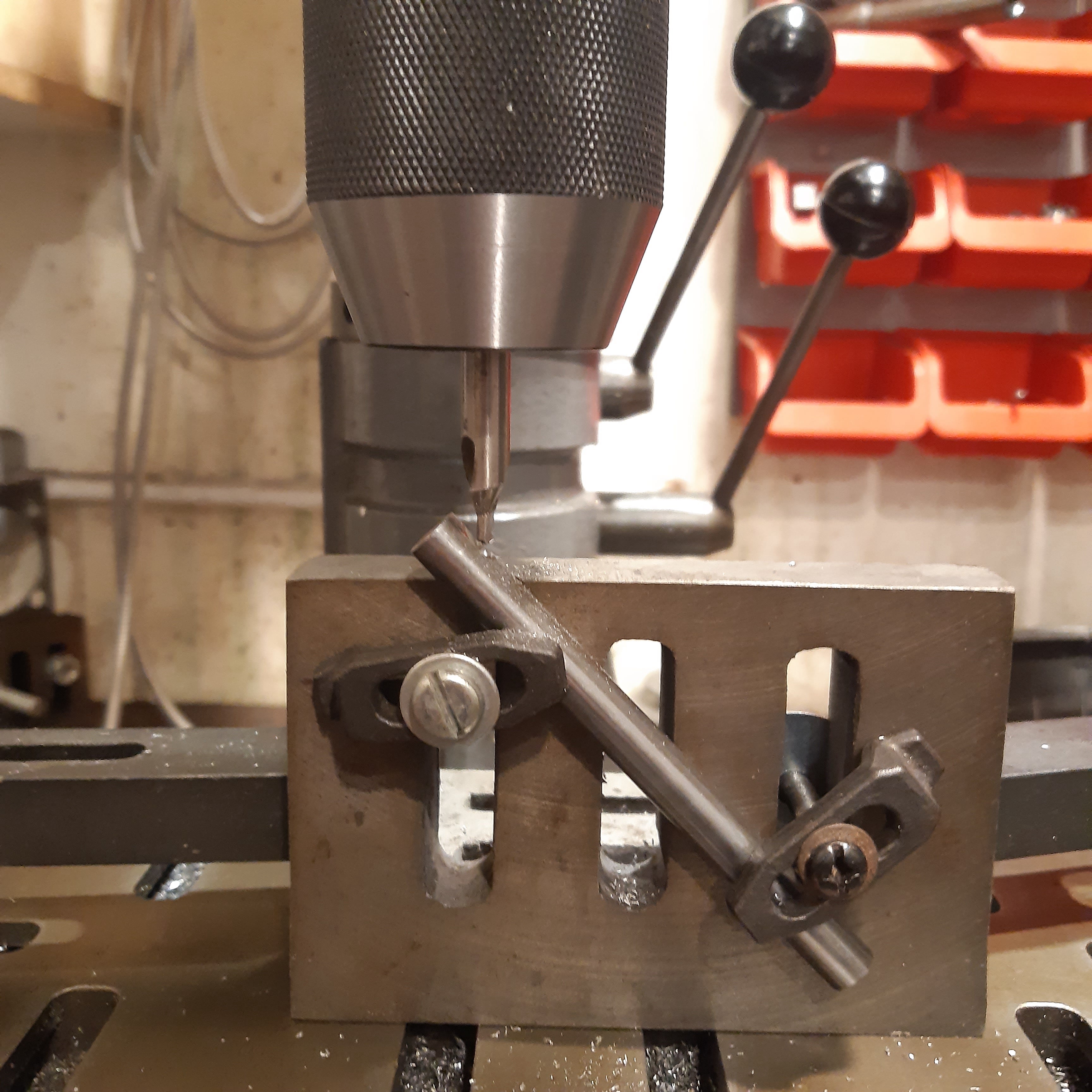
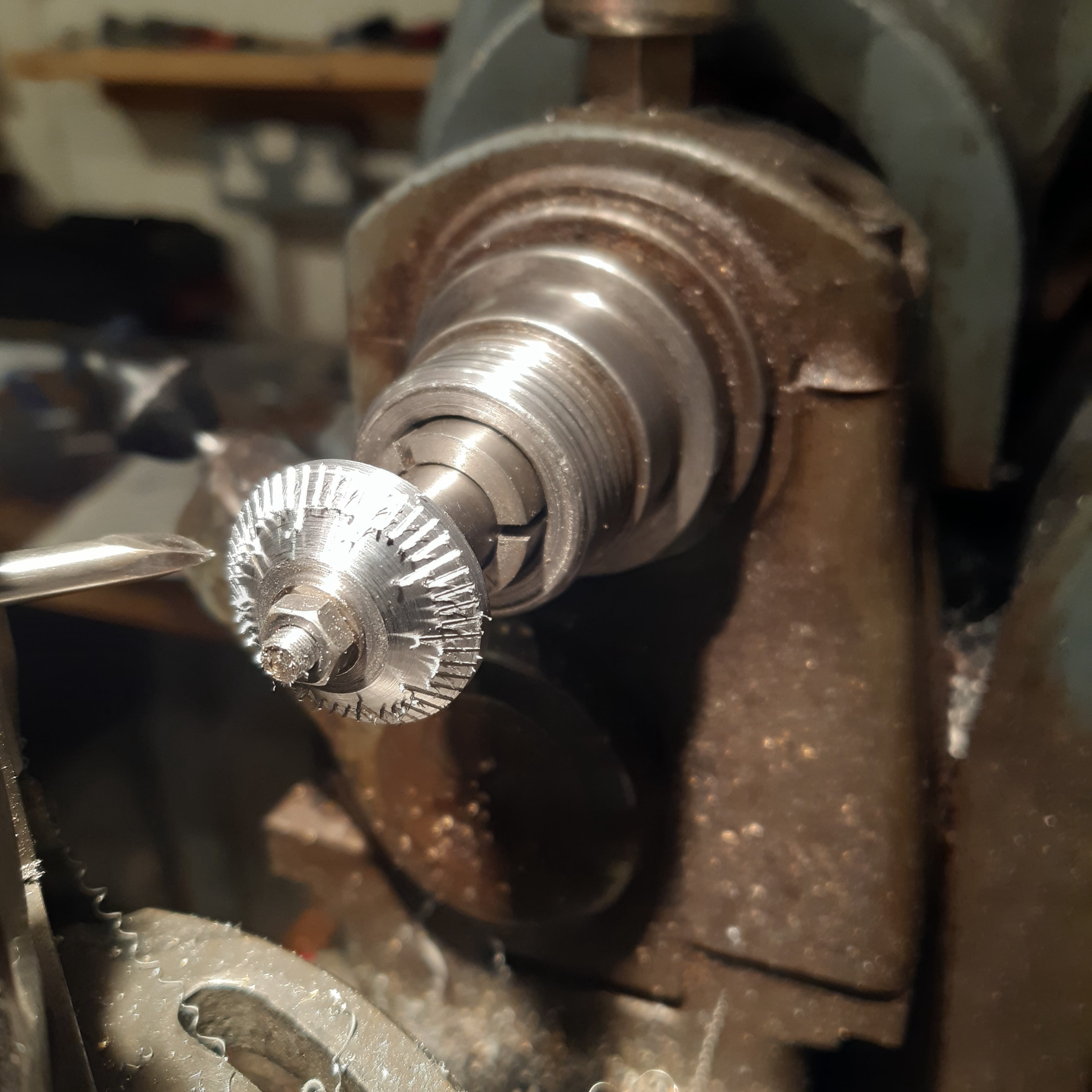
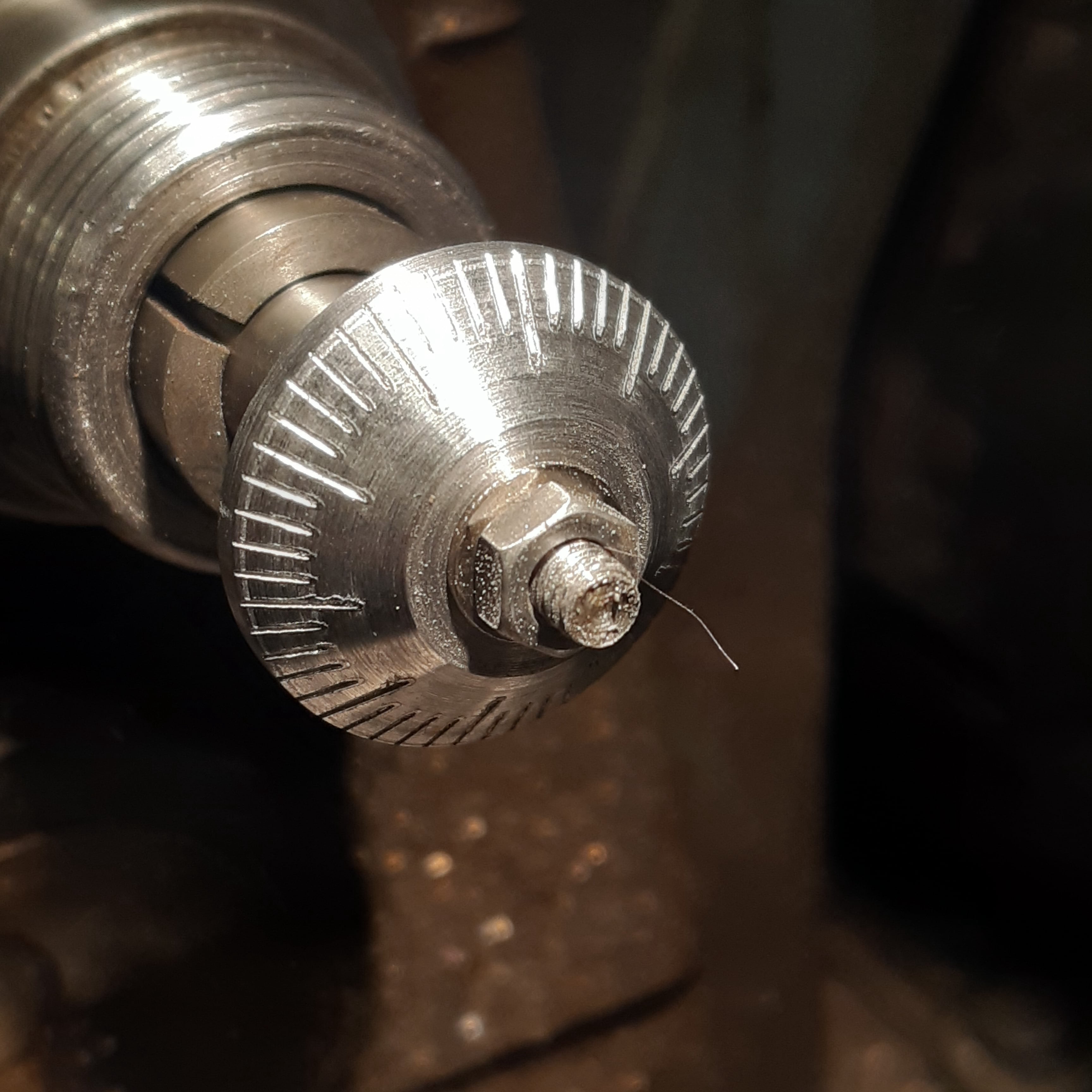
 The kit would require the machining of a dovetail slideway, so a 60 degree milling cutter was ordered.

This page is not intended to plagiarise the Hemmingway design (by Mr G.H. Thomas), but rather to add some images to the work instructions given in the kit.

Mobirise Website Builder

The kit from Hemmingway came with some useful notes, drawings, and the materials/fixings required. There were also suggested machining steps illustrated for some of the more complicated parts.

Mobirise Website Builder

The sliding member was machined first. The starting blank was not quite square on the cut faces, so the 4-jaw chuck was used to get all the faces at 90°.

Mobirise Website Builder

The blank part marked out for the adjuster hole which was then centred in the 4-jaw chuck....

Mobirise Website Builder

......and then drilled to size right through.

Mobirise Website Builder

The milling machine was used to cut the lower.......

Mobirise Website Builder

....and upper shoulders, as well as reducing the part to final width. Without moving the vice....

Mobirise Website Builder

.....a 60° dovetail cutter was used to cut the angled shoulders on the parts.

Mobirise Website Builder

The sliding member was turned in the vice to be drilled and reamed for the gripping bushes which would hold the boring cutter.

Mobirise Website Builder

The underside was sawn, milled and filed to create an under-cut.

Mobirise Website Builder

Then the tapped hole was counter-drilled, on the drill press, before....

Mobirise Website Builder

...the excess material either side of the nut was machined away.....

Mobirise Website Builder

...and then the nut was rounded with a file.

Mobirise Website Builder

The chamfer on the underside of the sliding member was machined with light cuts on the mill.

Mobirise Website Builder

The Housing. The cut ends of the housing block were squared off in the 4-jaw chuck and then the screw hole was drilled and counter-bored to the drawing.

Mobirise Website Builder

The mill was used to cut a slot through to the drilled hole and to rough out the shoulders for the dovetail.

Mobirise Website Builder

The dovetail cutter was used to create the dovetail to the drawing. Light finishing cuts were used on all the working surfaces to ensure parallelism, and minimal tool deflection

Mobirise Website Builder

A test fit with the sliding member showed a gap where the dovetails met. The problem seemed to be that the corner on the sliding member was sharper than the one in the housing.

Mobirise Website Builder

This was remedied by filing the point off the sliding member as shown above, to get the working surfaces to meet.
The result would be a fractional offset to the threaded nut, but this could be compensated for with the front plate positioning.

Mobirise Website Builder

Before removing the part from the mill, the housing was used to hold the gib strip for edge machining, in accordance with the instructions.

Mobirise Website Builder

The housing was rotated in the vice for drilling and tapping of the gib strip screws, and also adding detents in the gib strip using the set-up shown above.

Mobirise Website Builder

Then the 4-jaw chuck was used to machine the threaded hole for mounting arbor and skim the top face to final profile to ensure it was perpendicular to the hole.

Mobirise Website Builder

The cosmetic shoulders on the housing were added on the milling machine, using the set-up shown above.

Mobirise Website Builder

The adjuster thread was machined between centres and then thread cut to match the sliding member.

Mobirise Website Builder

A split collet was machined from brass to hold the adjuster thread so that the detail on the end could be machined.

Mobirise Website Builder

The adjuster nut was centre-drilled, drilled and threaded on the lathe.

Mobirise Website Builder

The lathe chuck was moved to the milling vice for cross-drilling......

Mobirise Website Builder

....before returning to the lathe for finishing and parting off.

Mobirise Website Builder

The end plate was prepared by drilling the centre hole and the two mounting holes.

Mobirise Website Builder

With the housing, sliding member, threaded rod and nut assembled, the position of the two mounting holes was then transfer drilled to the housing.

Mobirise Website Builder

The adjuster knob was made by knurling a piece of steel bar and then drilling, and tapping the internal thread, before cross-drilling on the milling machine.

Mobirise Website Builder

The locking screw was made by knurling a piece of steel bar and then cutting an external thread, before parting off the bar stock.

Mobirise Website Builder

The brass collet clamps were turned to the plans, including the flange which would be used to hold then secure for the drilling operation* for the boring bar.

Mobirise Website Builder

The universal MT-02 arbor was put in the lathe headstock and a thread was machined to match the housing.

Mobirise Website Builder

The whole boring head was now assembled onto the arbor. The marked position for the boring bar was set to run true by winding the adjuster screw.

Mobirise Website Builder

The position of the sliding member was locked with the gib screws and locking screw and then the end plate and adjuster screw were removed.

Mobirise Website Builder

* The hole for the boring bar was now drilled and reamed to 3/8". This operation would also cut the required notches in the brass collets.

Mobirise Website Builder

This photo shows a check fit of the boring bar in the sliding member collets.

Mobirise Website Builder

The flanges were then machined off both collets, to allow them to pull into the sliding member hole, to clamp the boring bar.

Mobirise Website Builder

This photo shows the brass collects re-fitted without their flanges.

Mobirise Website Builder

The back profile of the dial was machined first......

Mobirise Website Builder

....before fixing it to an arbor to have the conical face machined.

Mobirise Website Builder

With no dividing head, a paper sketch of the dial division was fixed to the rear of the lathe headstock and a height stand set up as an indicator.

Mobirise Website Builder

Without changing the top slide angle, a piece of a silver steel was ground to a sharp point and mounted in the tool post.

Mobirise Website Builder

Markings were scratched on the dial facing using the top slide handle. Two turns for the small division and three for the long ones.

Mobirise Website Builder

The dial was cleaned up with a file and then some abrasive cloth.

Mobirise Website Builder

A centre punch mark was added to the front plate, as an indicator.

Mobirise Website Builder

The finished tool

Drag and Drop Website Builder