A Bicycle Sidecar.
The Bicycle Sidecar was developed, so the whole family could go cycling together.
The Bicycle Sidecar was developed, so the whole family could go cycling together.
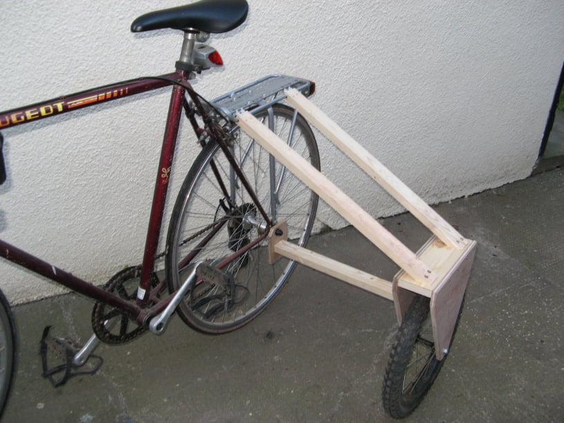
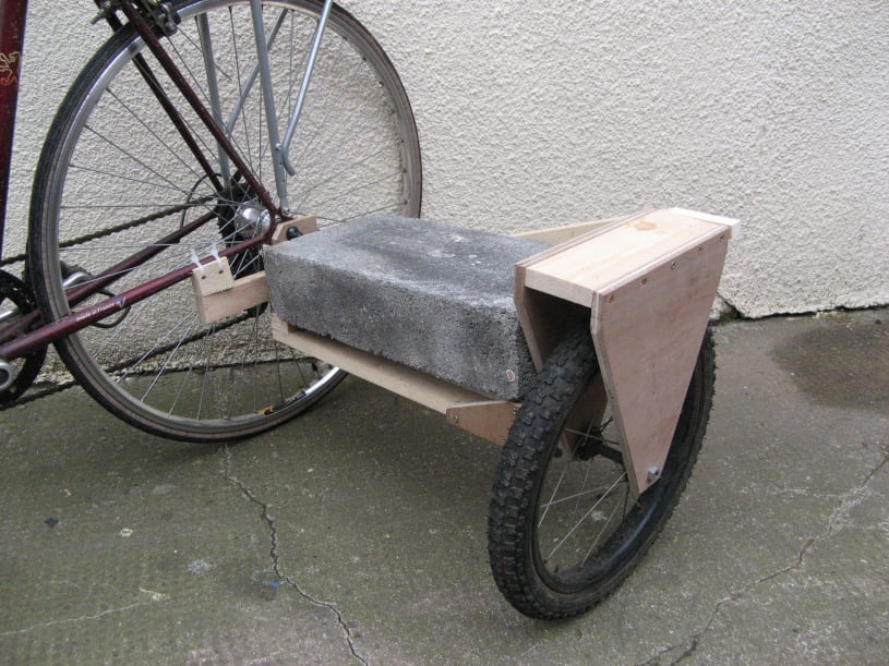
To test out the theory of a sidecar on a bicycle, a 3rd wheel was added to a road bike, to see how it handled.
The extra wheel was a 12" front wheel from a child's cycle (free from the local tip).
It was mounted in a simple plywood frame and was attached to the cycle with a 3 point mounting system. The lower mounting point was attached to the rear axle thread. The 2 upper mounts were joined to the luggage rack with cable ties.
On the road the extra wheel made cycling 'interesting'. Straight lines were no problem. Turning right as also acceptable whether you tipped the cycle to lift the 3rd wheel, or just let the extra wheel take the weight and cornered flat.
However turning left was a problem. The bike couldn't lean left because of the wheel and you couldn't corner flat because there was no wheel on the outside to give support.
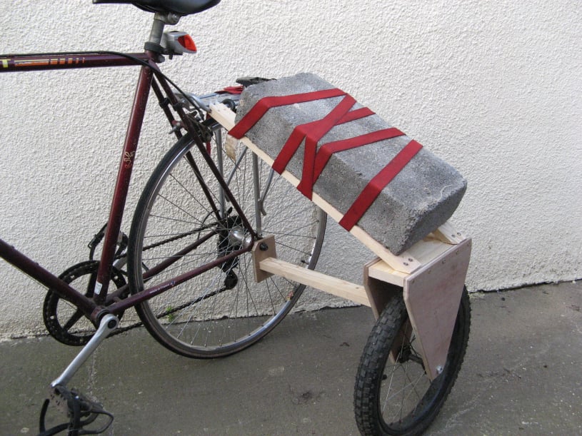
Next the extra wheel was loaded up with 18kg of ballast to simulate a sidecar with passenger.
This weighted set-up was impossible to ride safely.
Left hand turns became slightly easier, with the extra weight on the inside to hold the cycle flat, but everything else was worse.
Even travelling straight was difficult because the wheel would change the angle of the bike depending on the flatness of the surface it was travelling on. A change in the camber of the road could send the cycle careering one way or another.
This sidecar problem was confirmed by some text found on the internet which read :-
"Cycle sidecars have to be of the banking type because the rigid framed type used on motor cycles tend to lift the third wheel on every downward pressure stroke of the right hand pedal. Watsonian overcame this problem by making the inner member of the sidecar a tube which was attached to the bicycle by the means of two clamps secured by wing nuts. The ability of the tube to revolve within these clamps provided the necessary hinge. These clamps were on the lower edge of a plate which was bolted to the rear spindle nut and the chainstay & seatstay of the bicycle. The rest of the chassis was made of riveted flat steel strips and held a 14 inch wheel within a copious mudguard. Two levels of wheel mounting were provided to allow for attachment to cycles with 26 or 28 inch wheels. The chassis was said to carry up to 112lbs in weight."
Quote taken from the "National Autocycle & Cyclemotor Club" website.
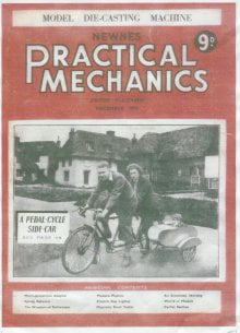
<- Further confirmation came from this article in 'Newnes Practical Mechanics' December 1950, which gave plans for a single seater sidecar which was mounted so that the cycle could tilt for greater controllability. The sidecar was made from an angle iron frame with an aluminium bodywork.
Based on this information, another wooden prototype was fabricated - this time with a pivot connecting it to the bike.
To allow room for feet on the pedals, the sidecar had to be mounted quite far back. The front pivot mounting was in-line with the rear axle and a second mount was 200mm behind this on a extended beam.
The sidecar was almost unnoticeable when the cycle was moving but getting started was different because the cycle couldn't be tilted to lift the required pedal. The reluctance of the cycle to tilt when stationary was because to tilt the cycle, the tyre would have to be dragged sideways.
The flexing in the wooden mounting meant that when pushing hard, there was a pulsing with each rotation of the pedals, due to the inertia of the weight in the sidecar, but this could be improved with a metal construction.
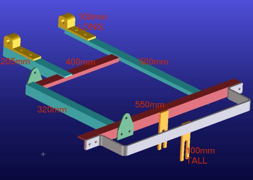
The CAD drawing shows the proposed frame layout with key dimensions. The angle iron was 25mm x 25mm x 3mm thick.
The height of the wheel mount was designed for the 16" wheel, but adjustment was factored in, for different towing cycle heights.
The main frame width of 320mm was chosen so 300mm wide coach-work could be made.
The 180mm distance from the main frame to the pivot was chosen to allow clearance for the pedal.
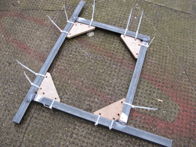
First the angle iron was cut to the required lengths and all the ends were squared off.
Areas to be welded were cleaned with a grinder and then the frame was assembled on a flat surface with some wooden right-angles to set things square. Cable ties were used to hold everything in place.
This image shows the basic frame completed.
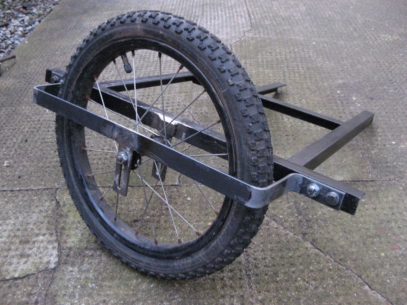
The wheel support had a slot to enable the sidecar to be height adjusted for different bicycles.
The outer wheel frame was a piece of bent 25mm strip steel (4mm thick). The bends had to be made fairly accurately to ensure the wheel would be a good fit between the mounts. This outer frame was bolted to the main frame rather than being welded, to allow the wheel to be removed.
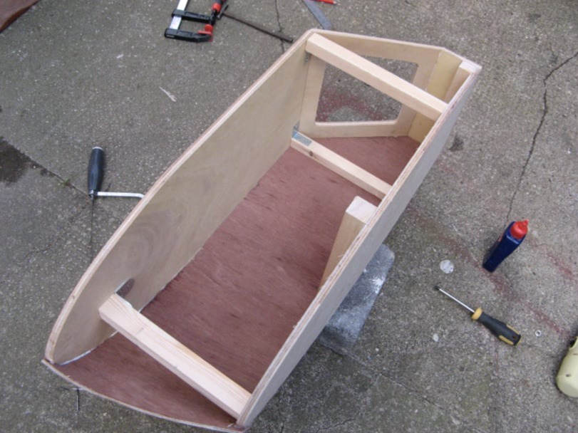
The sidecar bodywork was made with a 12mm plywood base and top. The sloping back was also 12mm ply and a hole was cut to allow access to the boot.
Softwood stand-offs were used to set the height and then a 4mm plywood skin was glued and tacked in place.
A boot hatch was cut at the rear
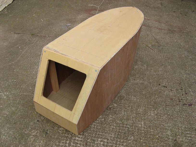
A section of the top panel was cut out and the sides were shaped, to form the passenger compartment.
A plywood piece was glued to each side to give the cut edge some strength and a grab handle was added at the front.
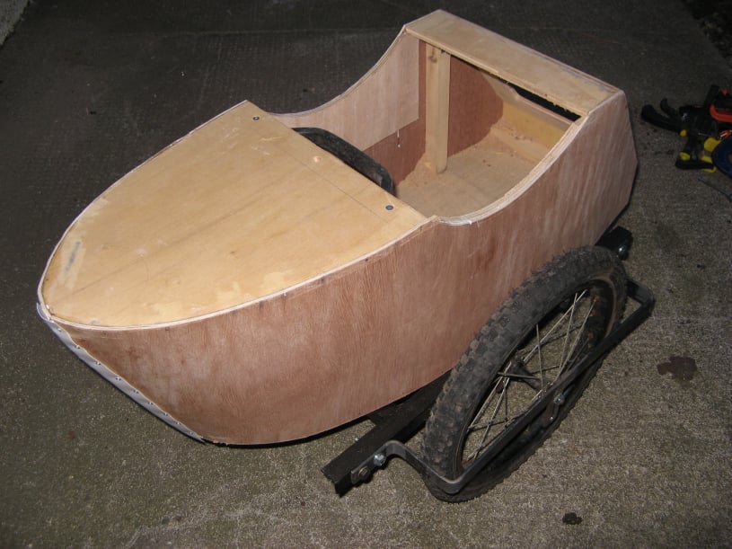
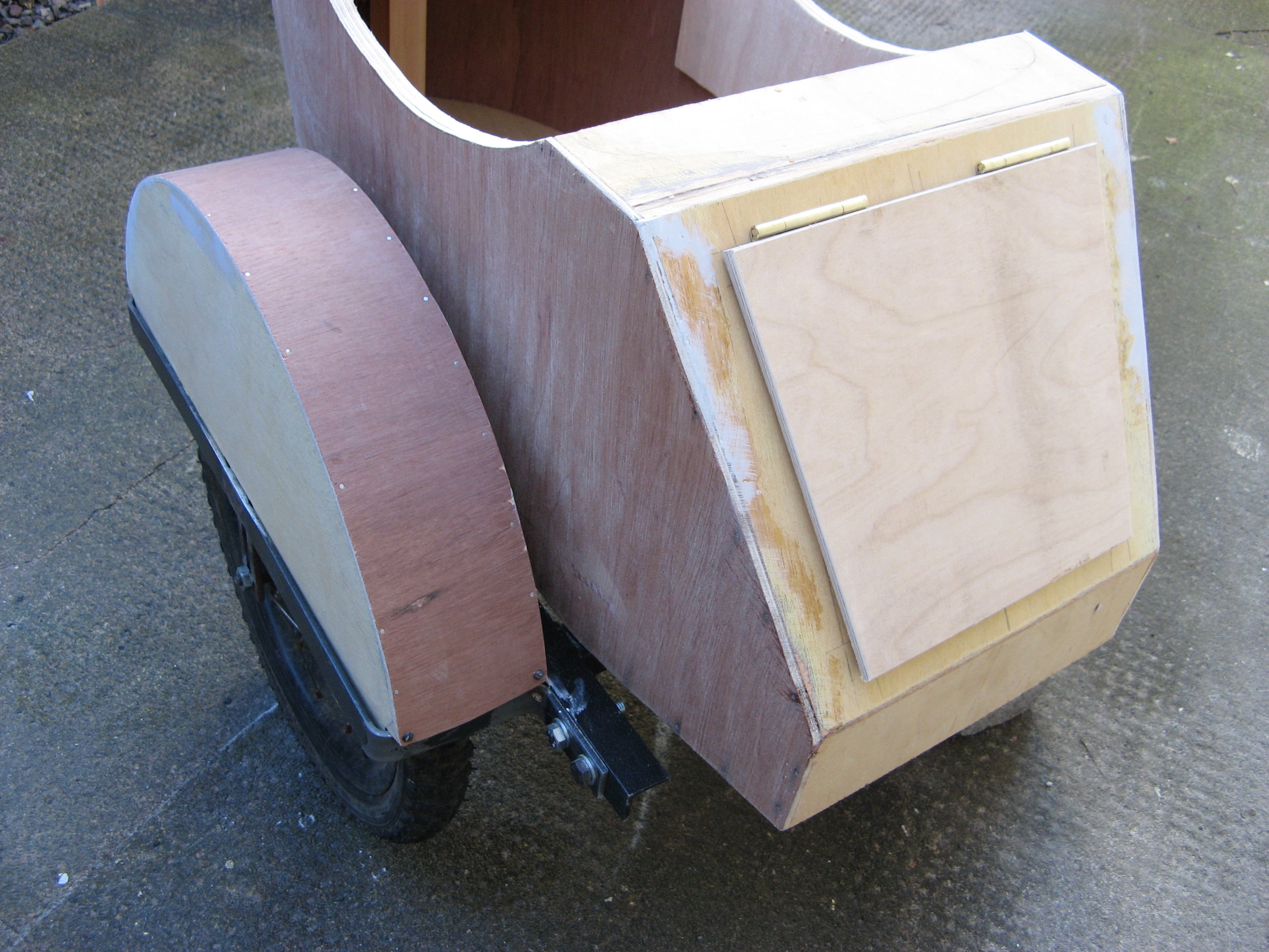
This photo also shows the wheel arch, which was made from 2 semicircles of 12mm ply with a 4mm thick curved top. This assembly was only secured to the inner frame so that the wheel could still be removed by unscrewing the outer frame.
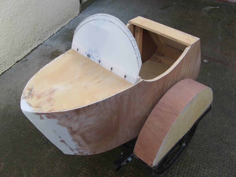
The boot lid was cut to shape and secured with 2 flush hinges and a magnetic latch.
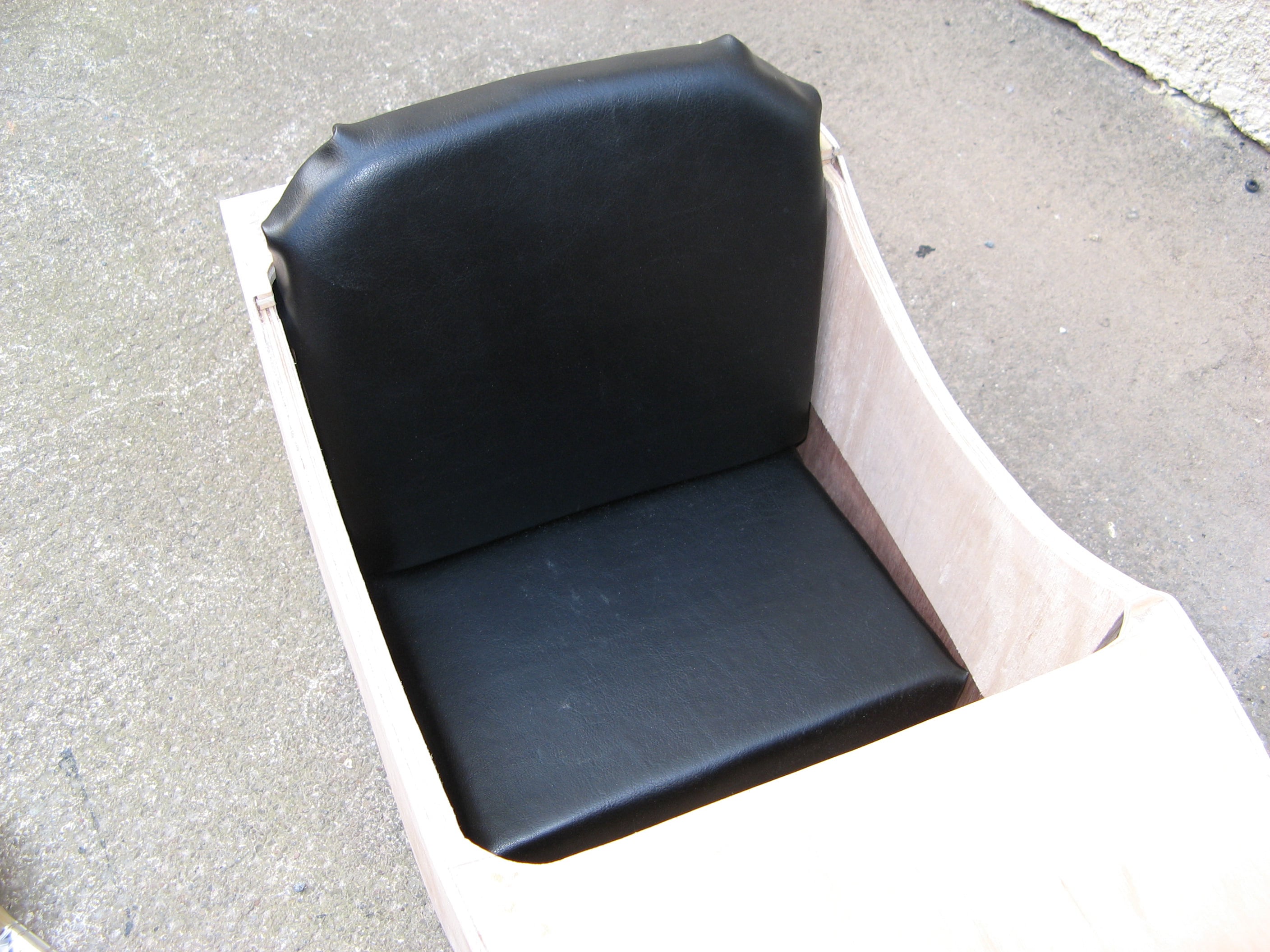
A simple seat was made from two wood panels with foam cushions.
Surplus camo paint from the Geepstar build was used to finish the bodywork.

The cabin was attached to the frame using some springs at the rear and some rubber stand-offs at the front as a pivot.
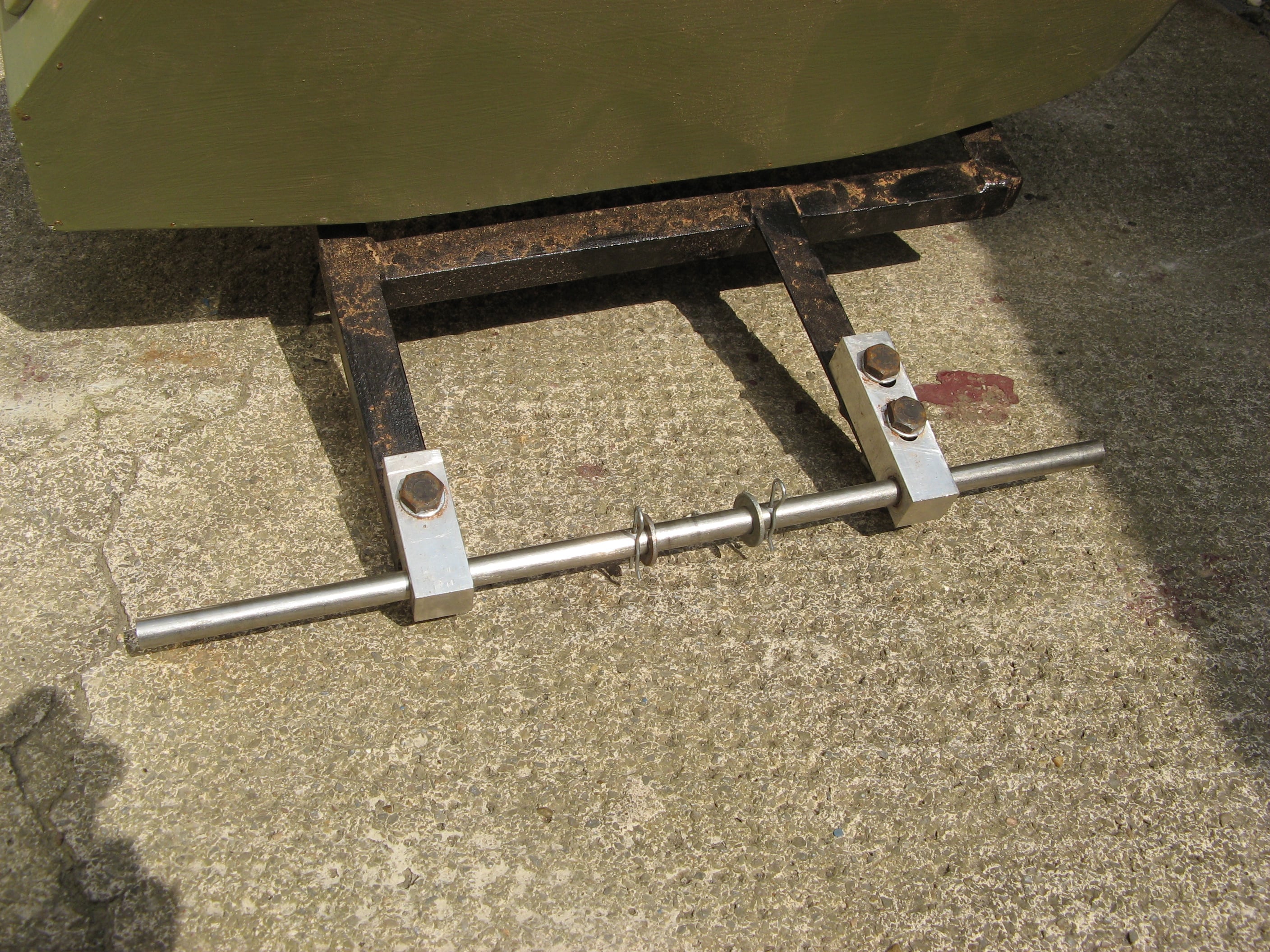
This image show the pivot bar which was a piece of 12mm stainless rod, cross drilled to take some securing "R" clips. The pivot blocks were 20mm aluminium bar.
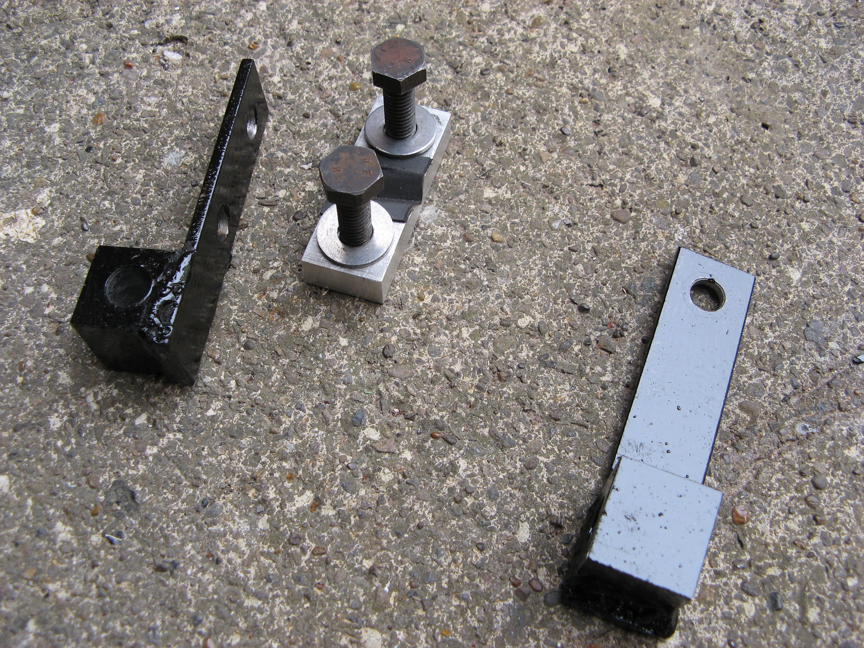
The bike pivot parts are shown above. The right hand part was designed to go on the axle nut, and the other pair of parts would clamp to the chain stay.
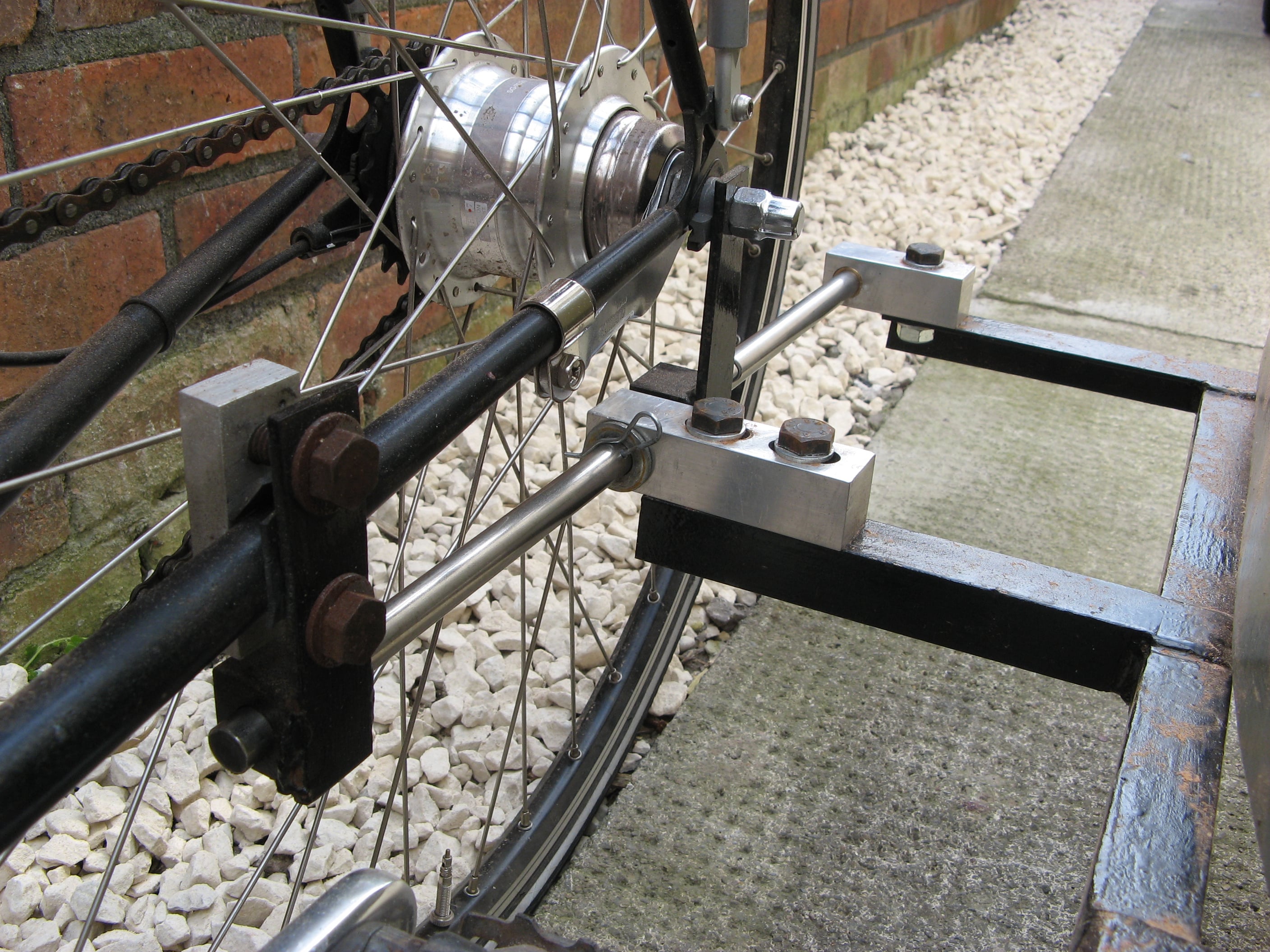
A view of the assembled pivot......
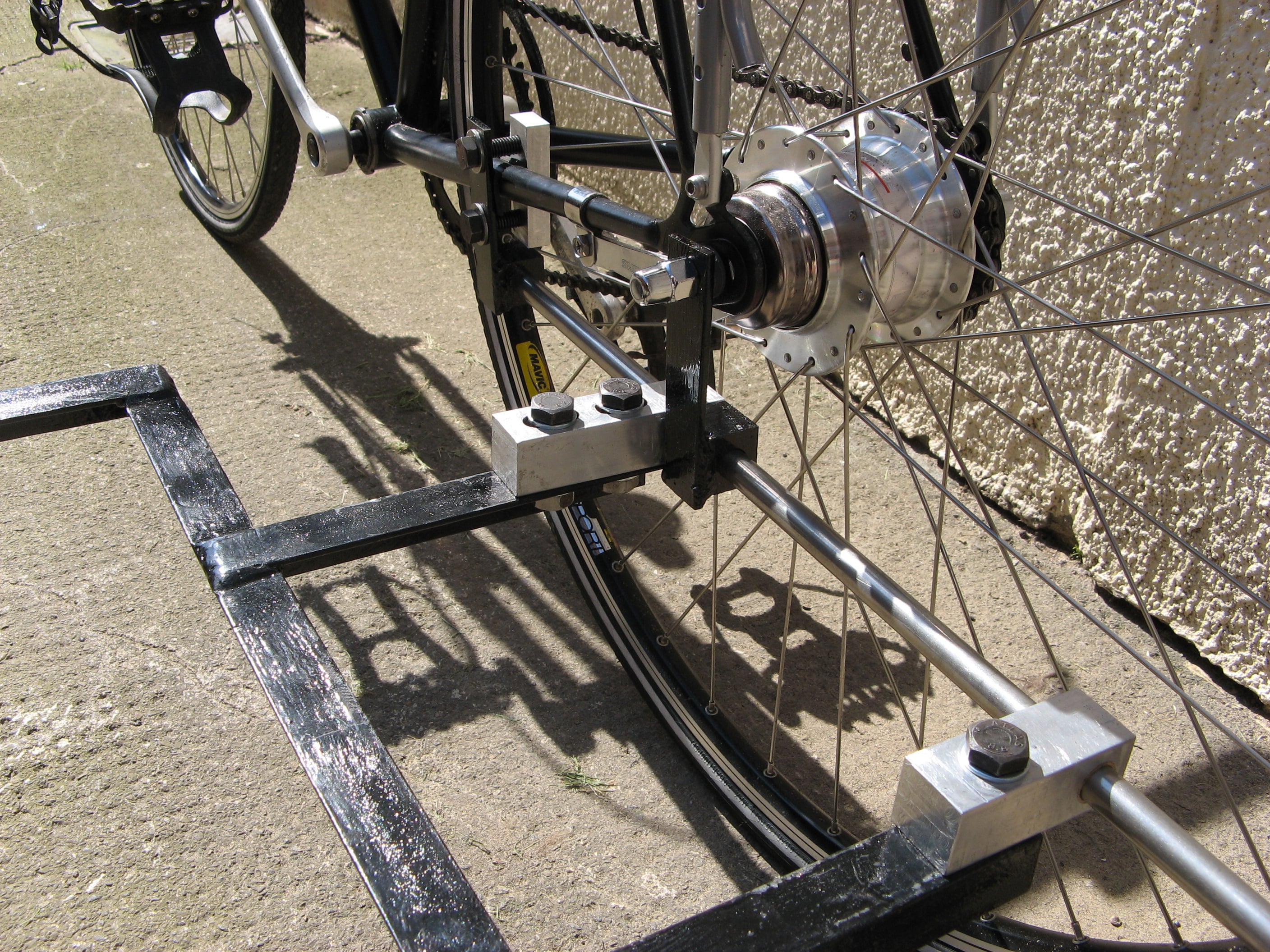
.....and another view.
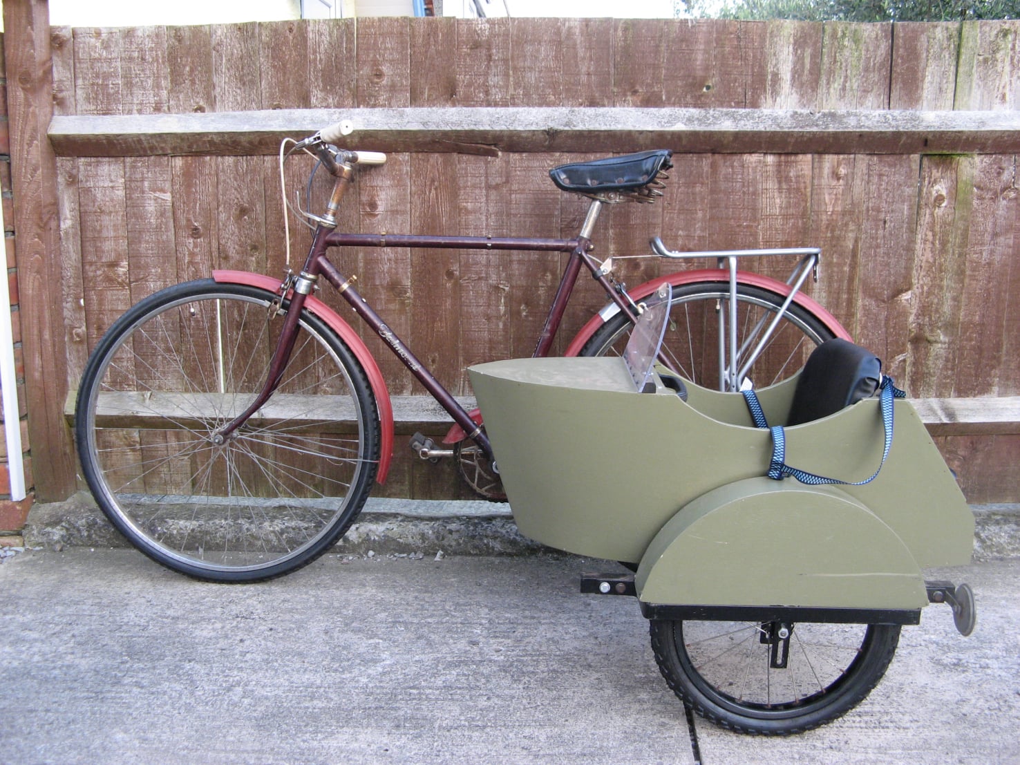
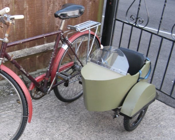
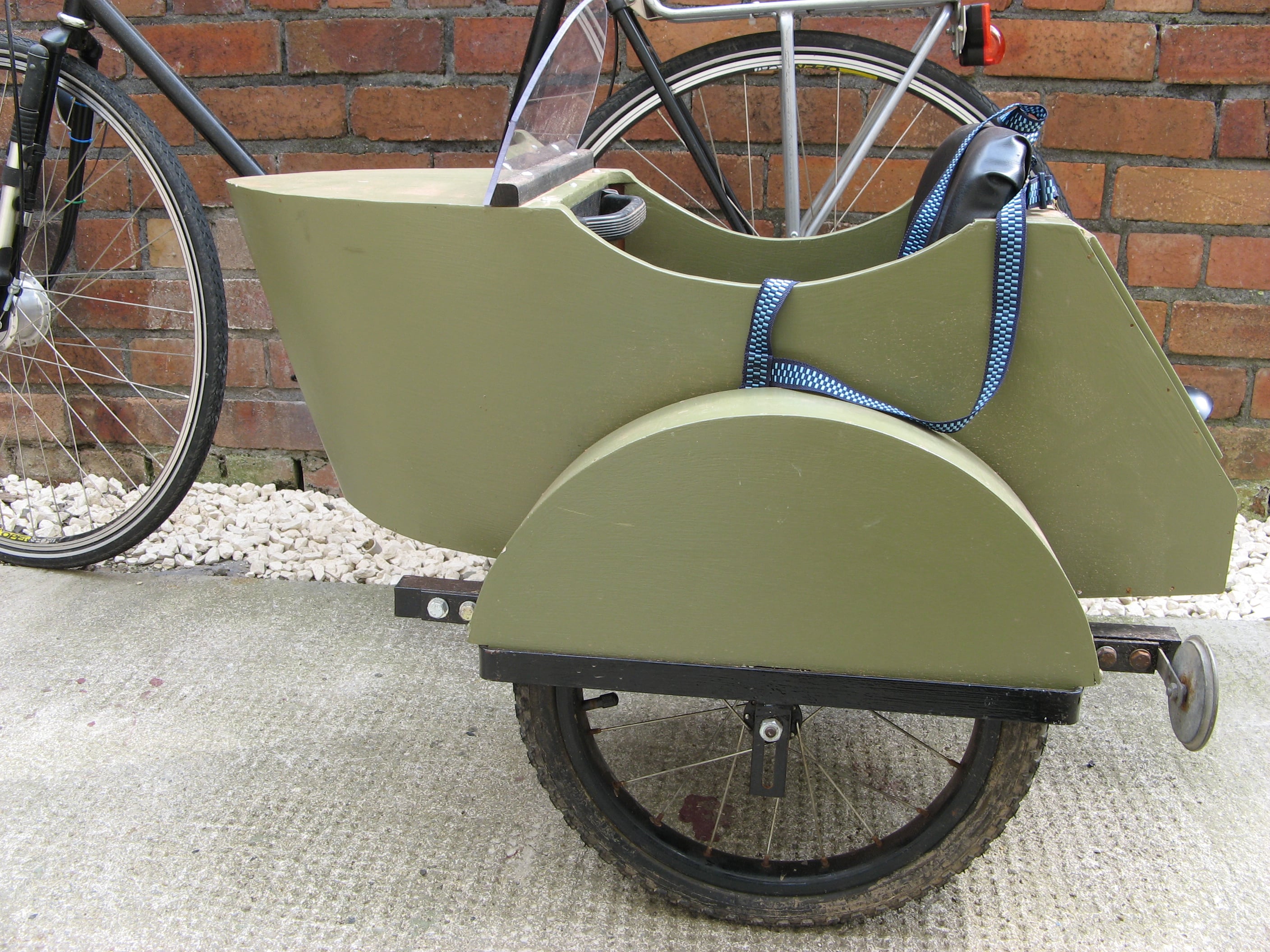
The finished sidecar coupled to the Hercules Balmoral bicycle.

Offline Website Software