Steam Tug
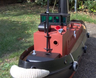
This Steam Tug was modelled using a fibreglass hull. The engine was a scratch built design and the superstructure was based on a 'TID Class Tug'
This Steam Tug was modelled using a fibreglass hull. The engine was a scratch built design and the superstructure was based on a 'TID Class Tug'
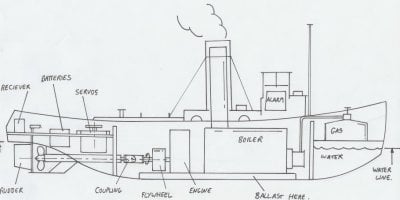
A plain fibreglass hull was purchased from Kingston Mouldings (sadly no longer trading). The hull came with scaled drawings of a full sized TID tug to help with the fabrication of the superstructure.
The first thing to be done with the hull was to work out how much weight would be needed to make it stable and sit at the correct height on the water. To do this the hull was placed in the bath and pints of water were added into the hull until it sat at the water line indicated by the plans. Then with some simple maths, the weight of the water inside the hull was calculated. In this case a total of 11Kgs would be needed to get the boat to sit at the correct level.
The layout of the inside of the hull was carefully planned. Considerations were made for the location of the engine, boiler, gas cylinder and radio gear inside the hull whilst bearing in mind the shape of the super structure, location of the funnel and rudder assembly.
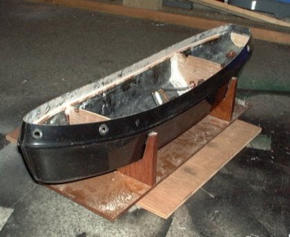
Once the layout was planned a simple stand made from plywood was constructed to hold the hull.
Inside the hull two 6mm ply bulkheads were glued in place and a deck supporting spar was glued along the moulded line.
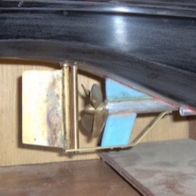
The propeller and shaft were purchased parts.
The shaft was aluminium bar, bored right through. The rudder and frame were fabricated from brass and the blue supporting webs were made from plastic off-cuts.
The inside of the hull was sealed and painted and the lower decks were added.
The rear lower deck had cut-outs for the control servos and radio gear.
The front lower deck covered a water/ballast tank and was also the support for the gas cylinder
Four brass studs were bonded into the hull to support the engine plate.
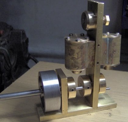
For maximum flexibility a reversible, self-starting engine was required. An oscillating design was chosen for simplicity and because it offered the possibility of reversing by just swapping the steam and exhaust ports. To enable the engine to self start 2 double acting cylinders would be needed 90º out of phase.
An engine was designed with a split crank. This would enable solid bearings to be used for the main support bearings and the big-end bearings. The crank would assembled using locking pins and Loctite.
A compressed air test confirmed that the engine worked as a whole and also that the reverse valve operated correctly. The engine ran quite smoothly even at speed. It was noticed that the reverse valve was also able to control the speed using its intermediate positions, but very fine control was needed to achieve this. It would need to be tested with the radio gear to see if this was a realistic method of regulation.
The torque from the engine was good and hopefully enough to power the proposed boat design.
At 20psi the engine was measured to be running at 1000rpm off-load.
Initially there were some leaks at the port faces. This was corrected with some polishing and lapping of the mating surfaces.
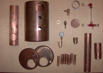
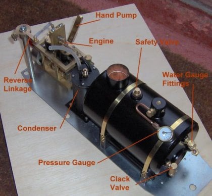
The boiler was made to a cheddar models design. It was an internally, gas fired 3.5" diameter, horizontal boiler. The parts to the boiler kit are shown on the left.
IN addition to these parts a condenser and manual top up pump were proposed for the final steam plant.
This photo shows the boiler plant before the plumbing was completed.
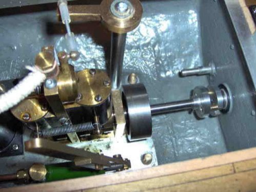
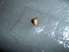
Another problem was highlighted when the plant was bolted into the hull. Despite best attempts to ensure that the output shaft of the steam engine and the propeller shaft were in line, the engine shaft had ended up fractionally too high. This meant that use of the originally proposed universal coupling was not possible.
Instead a coupling consisting of 2 discs, one with 2 driving pegs which located in the other which had 2 slots, was used. This joint was very tolerant of both radial and angular mis-alignment and worked well, although is was more noisy at speed.
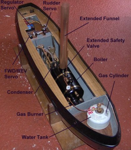
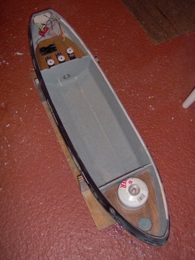
This image shows the tug hull with all the working parts installed
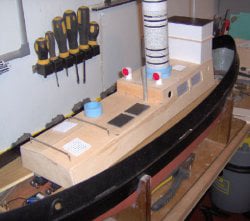
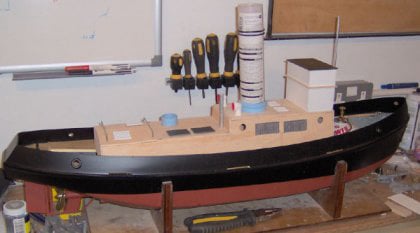
The super structure was fabricated using a mixture of wood, plasti-card, some model boat fittings and some odd scraps of material.
Parts were assembled with Superglue for initial location and then strengthened with a fillet of epoxy resin. All the construction was done in situ on the hull, to ensure a good fit to the deck.
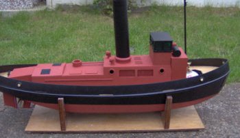
The model was painted in sanding sealer to hide the wood grain, it was then sprayed with a mixture of red oxide primer and satin black car paint.
The chosen colour scheme was somewhat basic but it was not far from being quite authentic. These tugs were built during the war and so the materials and paint were limited and the finish was not polished.
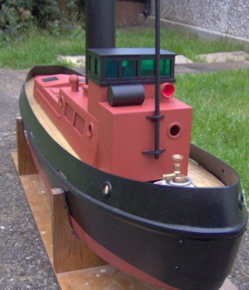
The final finishing touches included some basic rigging, a cover for the gas cylinder, some navigation lights some car tyres on each side and some rope fenders front and back.
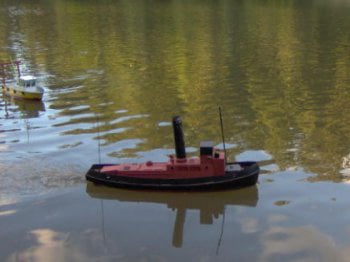
Out on the water the tug sat level and the ballast looked to be about right. Steering was good but at 11kgs in weight braking was quite tough. Speed and acceleration were not high either but it looked and sounded great.
Conclusions
The steam tug was not fast, in fact at a distance it was difficult to see if it was moving at all!
In the light breeze on the test day it was fine, but it would struggle on a more windy day or in faster flowing water.
Close up it sounded great and the steam from the funnel look good.
The condenser worked perfectly and no oil was left in the lake.
The regulator on the third radio channel was not needed, the boat could be driven on just the reversing valve.
The engine leaked a fair bit of steam at the reverse valve causing a lot of condensation inside the boat. At the end of the run 20ml of water was extracted from the hull.
The water alarm worked (set off by the condensation).
The boiler could maintain a steady continuous operation of the engine.
There were no breakdowns during the 1 hour sailing.

No Code Website Builder