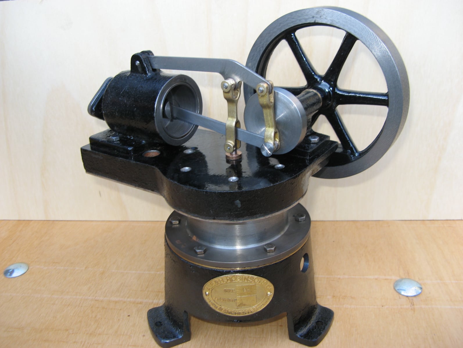
Robinson Hot Air Engine
This page details the machining and assembly of a 1/3rd scale Robinson hot air engine kit supplied by Polly Model Engineering in the U.K.
This page details the machining and assembly of a 1/3rd scale Robinson hot air engine kit supplied by Polly Model Engineering in the U.K.
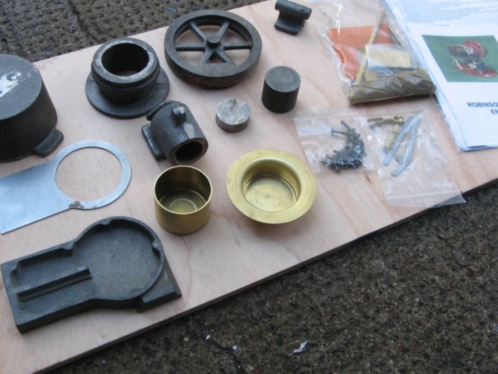
The casting kit contained six major cast iron parts. The hot cap and displacer piston were spun brass parts and the cover plate and links were already laser cut.
Also included was a bag containing small pieces of bar stock and another bag with all the fixings and some instructions.
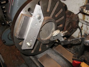
The engine stand was clamped to the faceplate so that the top face could be turned and the centre hole bored out.
The feet of the casting were dressed with a file to make a clean datum surface and the whole casting was centred so the outside rim ran true.
The hole was tested for size with the brass spun hot cap and it was found that a generous chamfer was needed on the inside edge to get it to sit down square.
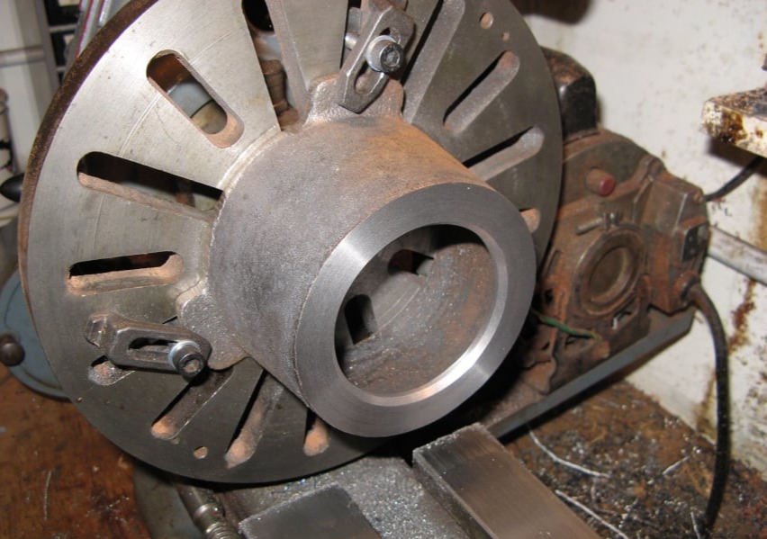
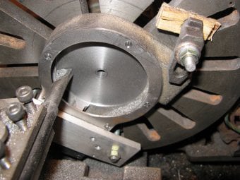
To cut out the legs the base was mounted on the rotary table as shown. This not only allowed the material between the legs to be machined but also a radius on the outside edges of the feet themselves.
To finish this part the 3 feet were drilled to take the mounting bolts.
Next to be machined were the engine base and the cover plate. The cover plate was a laser cut part which just had to have some holes drilled to finish it. However it was noticed that 2 of the 7 holes which were marked by the laser cutter didn't line up with the bosses in the casting, so these holes had to be moved accordingly.
After this, the holes were drilled and countersunk as shown on the plans.
The cover plate was then used as a template to drill the base casting by clamping the two parts together and transfer drilling.

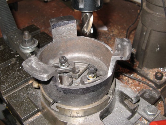
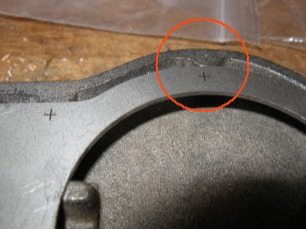
It was difficult to clamp the base casting to the milling table to machine the top and bottom surfaces. In the end a piece of plywood slightly thinner than the base, was cut on the bandsaw to match the shape of the casting. The casting was clamped into the wooden frame using some screws across the cut where the blade had entered the profile (circled) and then the wooden frame was clamped to the milling table. The results were adequate and enabled the top and bottom faces to be machined without moving clamps etc....
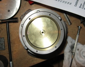
The base and cover plate were assembled and clamped to the lathe faceplate. The parts were adjusted until the circle in the cover plate was running true. In this setting the hole for the displacer bush was drilled and reamed and the underside profile machined to the drawing.
A boring tool was used to cut this area and the rim of the cover plate was also skimmed to make it perfectly round.
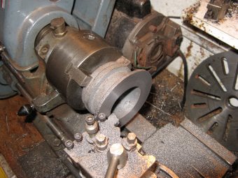
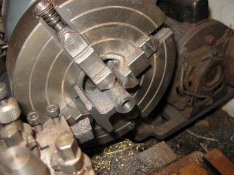
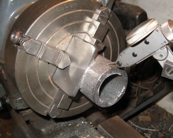
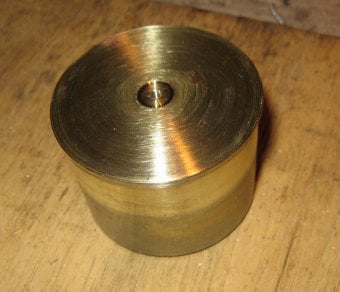
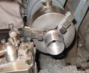
The displacer cylinder was placed in the 3- jaw chuck wit the lower flange mounted outwards. In this setting the flange was machined flat to create a datum surface. Light cuts were taken because of the long overhang of the part.
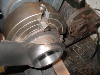
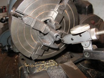
The part was mounted in the 4-jaw chuck and set so the outside of the casting ran true. In this setting the top edge, bore and top rim were all turned. This would ensure that the bore was perpendicular to the top edge, which would hold the displacer piston alignment.
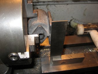
The cover plate was used as a gauge on the top flange diameter. Once the diameter was correct the assembled engine base and cover plate were used to gauge the overall height of the top flange.
It was found necessary to have a generous chamfer on the top edge of the cylinder to get it to mate squarely against the base plate of the engine.
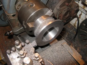
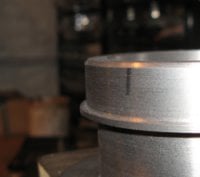
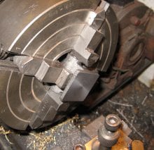
With the cylinder reversed again and held by the newly machined flange the outside of the lower flange was turned to its final diameter. Originally it was planned to leave the outside of the cylinder unmachined, but in the end some forming tools were used to skim the outside faces.
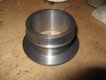
The finished displacer cylinder.
All the holes for this component were, later, transfer drilled from the mating parts.
The bearing housing was mounted in the 4-jaw chuck and clocked so that the outside of the housing was running true.
The face of the housing was machined and the front edge of the support also cut with the required offset.
The centre hole was drilled and reamed right through.
The casting was reversed in the chuck and clocked so that the hole was running true. Then this face was machined to take the casting to final length and the support recessed as before.
To finish the bearing housing base, the part was first skimmed on the underside and then each of the 4 sides in turn, using the 4-jaw chuck.
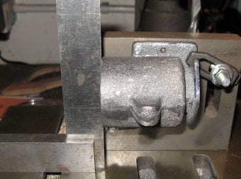
To machine the power cylinder casting, first the rough part was mounted in the 4-jaw chuck as shown and the top of the base lined up with a square against the lathe bed to get it correctly positioned in both axis.
The base was then skimmed to give a flat datum surface.
With the datum surface finished the part was turned round in the chuck and adjusted so the outside of the casting was running true.
Then the cylinder bore was turned along with the front edge of the cylinder and a 16mm hole in the rear.
Care was taken to ensue the cylinder was parallel by taking very fine cuts along the bore. The 16mm hole was non-critical.
To finish the rear flange on the cylinder, it was reversed in the 4-jaw chuck and off-set so that the full face could be cut without touching the mounting flange.
With the part removed from the 4-jaw chuck the 2 mounting holes were drilled in the drill press.
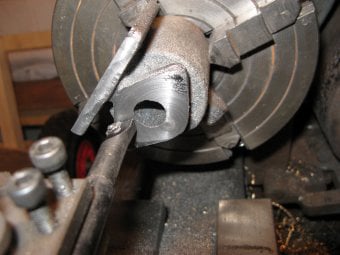
To cut the swing-link pivot on the power cylinder it was mounted on an angle plate on the mill and set square to the table bed. Then the pivot was drilled and slotted with a slot saw.
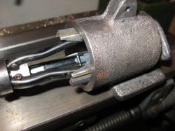
Finally the cylinder bore was honed to remove the machining marks. The hone was mounted in the lathe chuck and the part moved by hand up and down the honing stones. Light machine oil was used to aid the grinding process.
The only problem machining this part was the drilling and tapping of the two holes on the rear flange. The casting had become very hard in this area and a normal centre drill would only leave a very slight mark. After blunting many HSS drills a tungsten carbide drill was borrowed from work. This actually cut the hole with ease using a slow spindle speed and some coolant, but unfortunately it snapped as it broke through far side of the flange on the second hole.
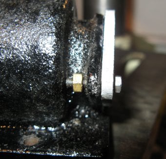
Tapping the hole was not possible but there was room behind the flange for a 6BA nut.
The displacer was made from the parts given in the kit, but to add more material where the threaded displacer rod was to be fitted, and extra block of brass was brazed to the inside of the top plate.
Next the displacer parts were brazed together and left to cool. No quenching was used to avoid distortion.
Once cool the outside of the brass plate was trimmed off using some metal shears.
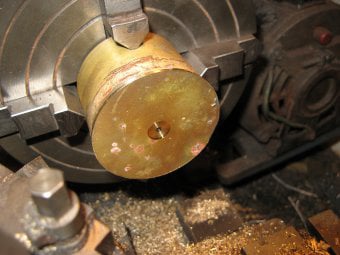
To ensure the displacer piston would run centrally in the displacer cylinder it was clocked in the 4-jaw chuck rather than relying on the 3-jaw for accuracy.
Once central, the edge of the displacer was trimmed so it was circular and the centre-hole was drilled and tapped. A recess was added around the hole to give the piston rod a square face to pull up against.
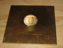
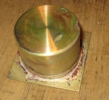
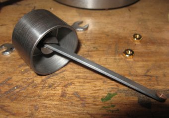
The finished displacer piston.
When the displacer was pushed into the cylinder it had three tight spot about its circumference due to the piston not being totally round. So the part was returned to the 4-jaw chuck and skimmed until it fitted in the displace cylinder with minimal clearance.
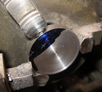
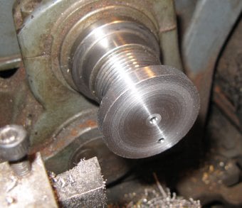
The crank disc was turned from a piece of steel bar. First, it was machined to just slight wider than the final size and then it was centre-drilled, drilled and reamed, to take the axle.
However - Before this drilling, the centre was just marked with the centre-drill and this was used as a datum to mark radius of the crank pin hole.
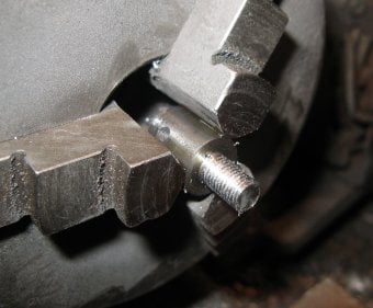
Next the part was mounted in the 4-jaw chuck and the crank-pin hole was centred so that it could be drilled and tapped.
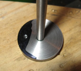
The axle was a piece of silver steel which was cut to length and then centre-drilled in both ends. This axle was then Loctited into the crank disc. Note that the crank face that was square to the drilled axle hole ie: machined in the same setting as drilling the hole, was pointing along the axle. So in the photograph shown on the right this face is pointing up. This was important because this face would be difficult to machine on the assembled crank but the outer face could be skimmed if needed.
To finish, the crank disc was held by the axle in a collet (or an accurate 3-jaw chuck) and it was turned to final thickness. The circumference was also skimmed to ensure it ran true. This was all done with a slow spindle speed and with light cuts to avoid tool chatter. The work was kept cool so the Loctite didn't become loose.
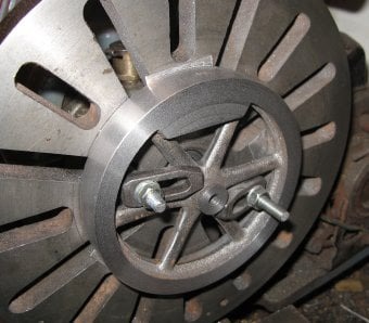
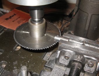
The flywheel was machined on the faceplate. It was clamped with three packing pieces behind the rim, and then adjusted so that the inner rim of the flywheel was running true. This inner rim would remain unmachined in the final part and so it needed to be set true before any machining was started.
Once centred, the rim, boss and centre hole were all machined in the one setting. The counterweight was also recessed slightly from the rim using a boring tool. The packing pieces allowed the outside rim to be completely machined without damaging the faceplate.
Next the flywheel was reversed and mounted in the 3-jaw chuck using the external jaws.
Then the other side of the rim, the boss, and the counter weight were machined to match the first side.
This secondary operation could also be done on the faceplate and this would be more accurate, but because the flywheel would be finished later on an arbor, the 3-jaw was good enough.
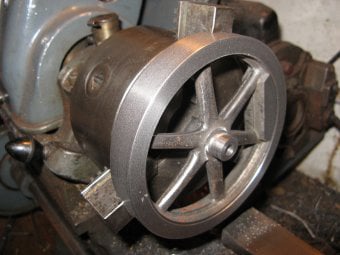
Before finishing; the spokes and counter-weight were painted so that a neat line would be left between the rim and paint.
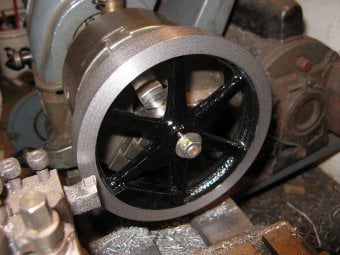
Once the paint was dry, an arbor was machined from a piece of scrap steel so that it was a smooth fit in the bore. This arbor would be exactly inline with the centre of the lathe and so with the flywheel held in place with a nut, the rim could be skimmed on all sides to make it run perfectly true. Light cuts and a low back-gear speed were used to prevent the flywheel chattering and creating marks in the rim.
The piston was machined from cast iron. It is important that pistons are round, parallel and smooth. A barrel or conical piston will not work well.
To get a nice sliding fit in the cylinder the piston was machined to a tight fit using the cutting tool on the lathe and then polished with some 1200 grip emery cloth to finish.
Once it was a nice fit in the cylinder, the block was drilled right through with a 1/4" drill and the bored out to make it as light as possible.
The gudgeon block was first cross-drilled with a 3mm hole to take the pivot pin.
Then it was placed on the milling table and the slot cut with a slitting saw. To get the slot perpendicular to the hole, a 3mm drill placed in the hole enabled it to be lined up by eye against the column of the milling machine.
Next the gudgeon block was placed in the lathe and the reduced shank turned to 1/4" and threaded 32tpi.
A nut to fit this thread was not included in the kit and so a 6mm metric nut was drilled out and tapped on the lathe to suit.
The finished piston/gudgeon block assembly
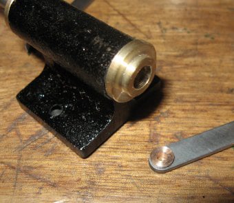
Various bushes for the crank and links were machined from phosphor bronze. The cast links were also drilled and reamed.
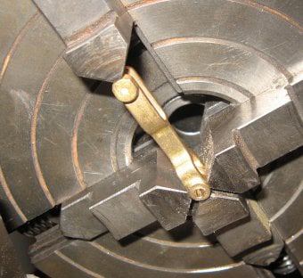
The links were drilled in the 4-jaw chuck to ensure the holes would be square to the external shape.
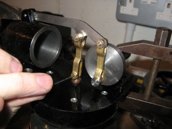
To drill the pivot link hole in the top of the displacer cylinder the engine was assembled without the piston and connecting rod. Then with the crank in lowest position and the displacer cylinder resting at the bottom of its stroke the rod was marked through the hole in the link.
Next the crank and displacer were raised to the top of their strokes and the rod marked again.
Assuming that the displacer travel is greater than the crank throw, then this process should provide two marks on the rod. Drilling mid-way between these marks should ensure that the displacer piston's travel is centred about the height of the displacer cylinder.
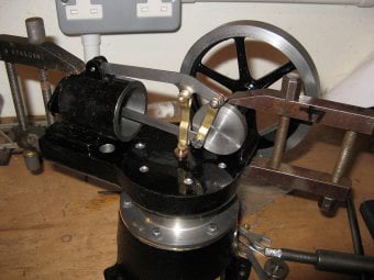
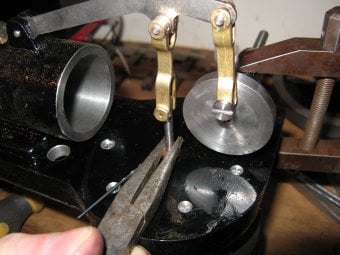
To drill the final locations of the cylinder and main bearing, the engine was assembled with all the links and the parts positioned around the displacer rod until things turned over smoothly. Then the holes in the parts were transfer drilled into the top plate and tapped 4BA. The hole to let the air into the power piston was also now drilled in the cylinder, to line up with the hole in the top plate.
During this assembly, it was found necessary to shorten the top of the displacer rod to stop it fouling the connecting rod.
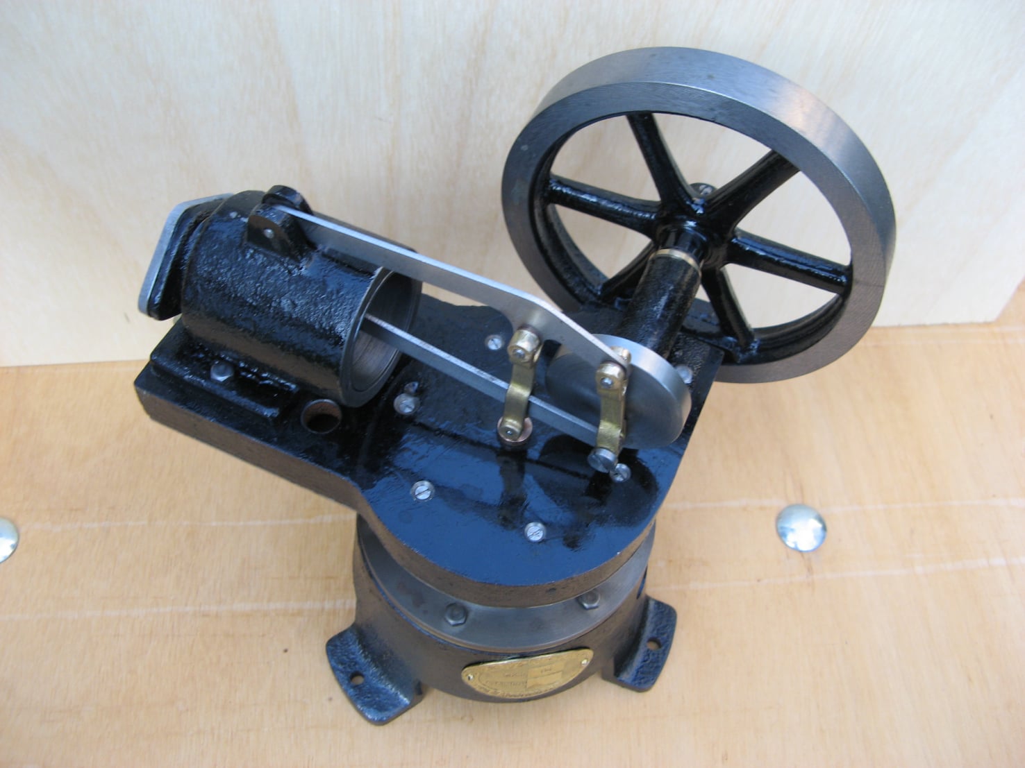
On the first test run - the engine failed to start. It turned over very smoothly but wouldn't run. Investigation showed some air bubbles in the water jacket when the power piston entered the compression stroke indicating a leak between the air channel and the water jacket. This was confirmed by traces of water in the displacer cylinder. To fix this, the displacer cylinder was removed and replaced with extra sealant around the mating surfaces. Sealant was actually pushed into the air channel and then punctured though after it had dried to ensure a watertight seal.
Click for a video on the engine running on a gas flame

Drag and Drop Website Builder