Mobirise Website Builder

Gauge 1. Girton - Tender

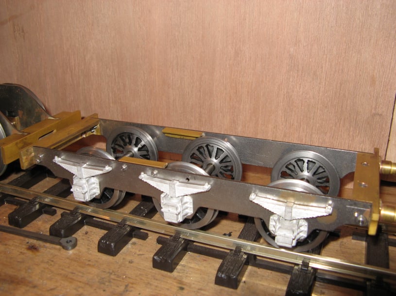
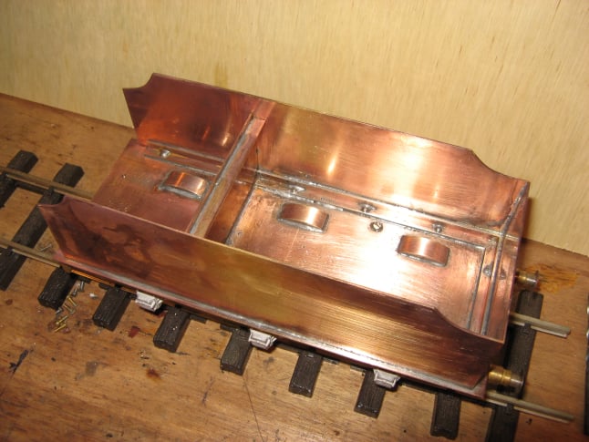
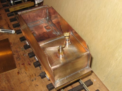
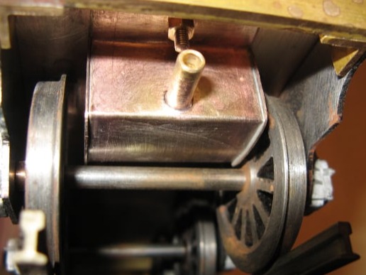
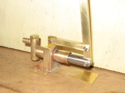
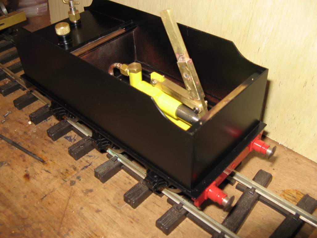
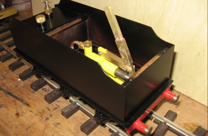
The Tender was a 6 wheeled design, with steel frame and brass plate-work. The tender was designed to hold the fuel (alcohol) and a fuel feed system. It also had a large water tank with a hand pump to feed the boiler whilst under pressure.

Mobirise Website Builder

The frames were laser cut by "Model Engineer's Laser". These not only had the finished profile but also the location for the axles marked on them.
The frames were joined with some brass angle buffer beams.

The 6 wheels were turned from castings provided by Walsall Model Industries. The axles were also turned along with bushes for the frames.

As the tender was unsprung, there would be a tendency for one axle not to turn because it would not be in contact with the rails. To avoid this the bearings for the centre axle were drilled 0.1mm oversize to allow the axle to float ensuring it would contact the rails.

To finish, white metal cast springs (also Walsall Model Industries) were super-glued to the outside of the frames.

Mobirise Website Builder

However - There was a problem with the wheel diameters. The tender was about 2mm lower than the locomotive. The buffer height was consequently too low.

To fix this some larger wheels were turned, but these protruded above the top of the frames, by about 1mm, which meant the plate work base would not longer fit.

Mobirise Website Builder

So some wheel arches had to be added to the tender base to cover the wheel rims. These were made by taking some slices from a large diameter piece of brass bar.

Mobirise Website Builder

The six blocks of curved metal were then soldered in place on the tender base.

Mobirise Website Builder

Finally the underside of the wheel arches were recessed using a bull-nosed cutter in the milling machine. This gave the clearance needed over the wheel flanges.

Mobirise Website Builder

The tender plate work was made from 1mm brass plate. The 2 sides were cut together to make a matching pair.
Brass angle was screwed to the base and then the sides were soft soldered in place. The mounting screws were also soldered to make the tank watertight.

Mobirise Website Builder

The fuel tank is shown on the left. Most important was that the tank was sealed and air tight for the feed mechanism to work.
The filler cap was sealed with an o-ring and also contained a dip stick to check the fuel level.
The feed valve was a simple screw down needle valve.

Mobirise Website Builder

Under the fuel tank there was a sump between the front tender wheels to set the fuel level in the burner. The outlet from the sump would be connected to the burner with a piece of silicone hose.

Mobirise Website Builder

The pump was made up as shown in the plans, but the base design was changed slightly to make it easy to mount and remove from the tender using a box spanner.
Bronze balls were used inside the pump body to make the clack valves

Mobirise Website Builder

Completed tender

Free AI Website Creator