Mobirise Website Builder

Gauge 1. Girton - Locomotive

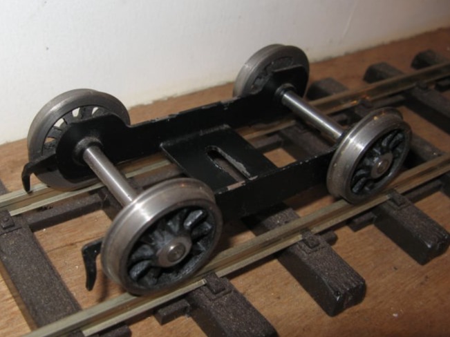
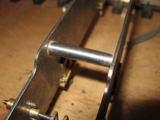
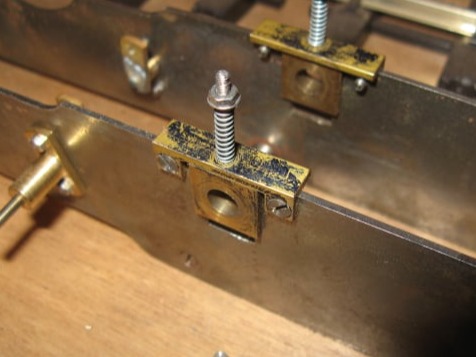
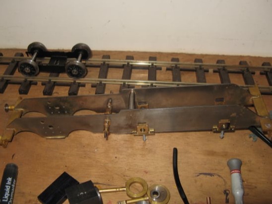
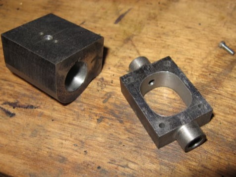
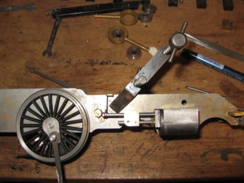
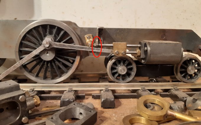
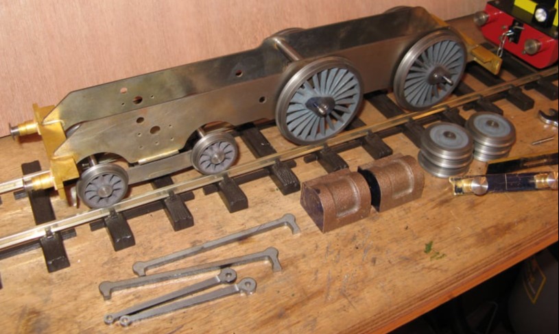
The main locomotive frames and the front bogie frames were all parts supplied in the kit of laser cut parts from Model engineer's Laser.
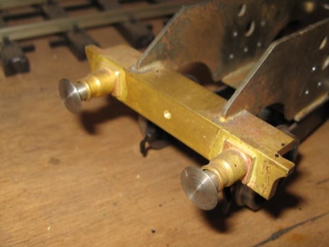
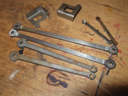
The kit also included some of the motion gear, and the tender frames.
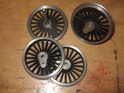
The wheel castings were supplied by Walsall Model Industries.

Mobirise Website Builder

The bogie frames were silver soldered together and bushed with bronze bushes to take the 6mm axles.
The wheels were machined from castings supplied by Walsall Model Industries. with the rims turned to the Gauge 1 standards and to the diameters marked in the plans.
The wheels were Loctited to the shafts to hold their position.

Mobirise Website Builder

The locomotive frames were supplied with the correct profile and with many of the drill holes marked by the laser. These holes were opened out to the correct size given by the plans. A stand-off was machined from 6mm steel rod to set the frames 30mm apart. This was secured to the frame using 2 counter-sunk 8BA screws.

Mobirise Website Builder

The buffer beams were cut from a length of 12mm brass angle. The sprung buffers were supplied by Walsall Model Industries and brazed in place.

Mobirise Website Builder

The axle blocks were machined from a piece of square brass bar. The slots in each side were cut with a 2mm slot drill in the milling machine. The hole was drilled and reamed to 6mm diameter. The axle block support was a piece of 6mm brass angle cut to length and with one section milled out. The holes were drilled and counter sunk to take some 8BA screws.

Mobirise Website Builder

The assembled frame.

Mobirise Website Builder

The main driving wheels were turned to the Gauge 1 standards and reamed with a 5mm reamer. The spokes were painted satin black before the final machining to give a neat finish.
The crank pin holes were drilled and tapped 5BA.
The axles were 6mm in diameter and were reduced to 5mm to suit the wheels. Two of the wheels had a axle was Loctited in place.

Mobirise Website Builder

The eccentrics were machined from steel bar. There were two parts to each assembly (the eccentric and the stop collar) to allow the locomotive to reverse.
The eccentric straps were made from a piece of brass bar bored to suit the eccentrics and with an arm soldered to connect to the rocking shaft. The straps were not of the split type so would only be removable by removing a driving wheel and sliding out the axle.

Mobirise Website Builder

The cylinder assemblies were machined from a piece of cast iron bar. The port face drillings were simplified by making them holes rather than slots. A CAD sketch was drawn up to calculate what diameter bar would be needed. This showed that a piece of 32.15mm bar was needed. 

Mobirise Website Builder

A piece of 35mm bar was ordered, long enough to create two cylinders and four end caps.

Mobirise Website Builder

The bar was milled as shown.....

Mobirise Website Builder

.....cut into two parts.......

Mobirise Website Builder

......then bored for the piston.

Mobirise Website Builder

Steam ports were marked out and drilled on the drill press......

Mobirise Website Builder

.....as well as the mounting screw holes and steam inlet.

Mobirise Website Builder

Front end caps were turned from a piece of cast iron bar......

Mobirise Website Builder

.....and drilled on the drill press.

Mobirise Website Builder

The rear end cap was similar but had a boss added on the milling machine

Mobirise Website Builder

The rear end cap was mounted on an arbor to turn a concentric shoulder on the back.

Mobirise Website Builder

The cap mounting holes were transfer drilled to the cylinder.

Mobirise Website Builder

Another piece of cast iron bar was milled flat and placed in the 4 jaw chuck to create the steam chest.

Mobirise Website Builder

The steam cheast cavity was milled on the milling machine.

Mobirise Website Builder

Piston blanks were machined from a piece of brass bar.

Mobirise Website Builder

These were then fitted to the piston rod and turned to final size using a collet chuck for concentricity.

Mobirise Website Builder

The laser cut connecting and coupling rods were prepared for an assmbly check.

Mobirise Website Builder

Unfortunately there was an issue 😕

Mobirise Website Builder

The problem with the Girton chassis is shown on the image above.
With the front wheel driving pin at top dead centre the connecting rod was perilously close to the bracket which supported the guide bar.
This became an interference when the suspension was compressed.

Shortening the guide rod, tilting the cylinder or lifting the cylinder wasn't enough to make it work.

For this reason the locomotive was changed for the Project design.

No Code Website Builder