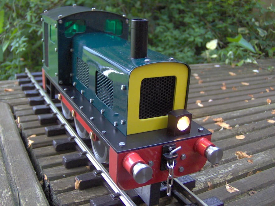
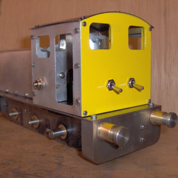
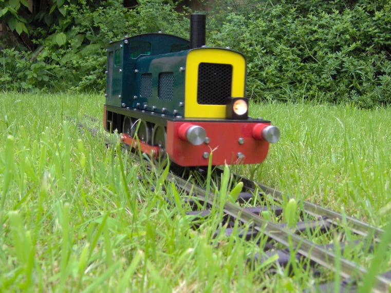
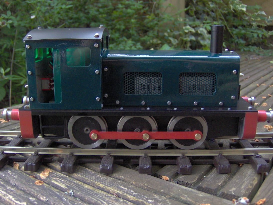
Gauge 1. 0-6-0 BR class 08 locomotive
This simple locomotive was built primarily as an exercise in machining coupling rods.
To keep things simple it was designed to be battery powered rather than use a line pick up system.
This simple locomotive was built primarily as an exercise in machining coupling rods.
To keep things simple it was designed to be battery powered rather than use a line pick up system.
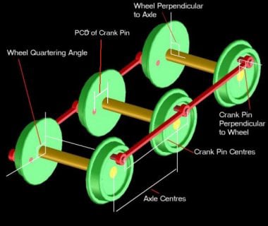
Coupling rods are tricky components to make. They are ideally loose enough to be a running fit but are not so loose that they rattle or have slop in them. This is difficult because of the build up of tolerances which occur in the whole system as shown by the diagram on the left.
To get a smooth running fit........
- The PCD of all the crank pins must be the same. The exact distance is not important but they all need to be the same.
- Each crank pin must be parallel to the main axle, which should also be perpendicular to the wheel.
- Each axle must have one wheel's crank pin, set at 90º to the other. This exact angle is not important but again all the axles must have the same angle (known as wheel quartering).
- The distance between the holes in the coupling rod must be the same as the distance between axle centres.
If all these parameters are exact, the coupling rods should run smoothly.
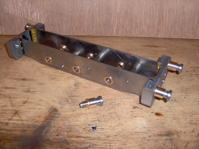
The frames were drawn out on 2 pieces of 1.5mm steel, clamped together. These parts were then cut to shape and drilled and reamed to make a matching pair.
3 stand-off's were machined from 10mm steel bar. No stand-off was used at the back of the frames to allow for the motor drive assembly.
The stand off length was calculated to give the correct wheel spacing as per the UK Gauge 1 Association guidelines.
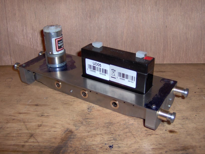
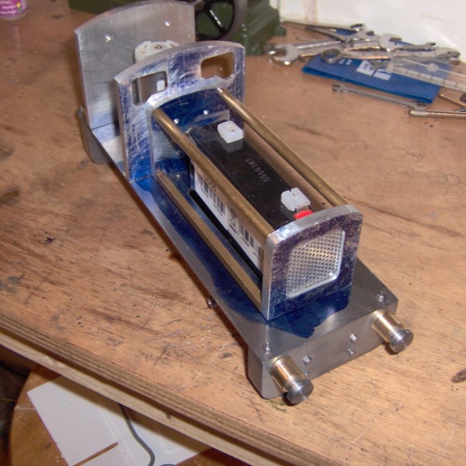
The design was based around a 6v lead-acid battery and a geared motor fitted with a worm drive to the back axle. Transmission would be passed to the other 2 axles via the connecting rods.
This photo shows the top plate with cut outs for the battery and motor. The battery was a 6v lead acid cell and was supported by the front 2 frame stand-offs.
The motor had a reduction gearbox and a worm drive directly coupled to the back axle.
The bodywork was made from Aluminium with some brass and steel off-cuts used as required.
The 4 main formers (2 for the Bonnet and 2 for the Cab) were cut from 6mm Aluminium, they were made in matched pairs to ensure good symmetry. The windows and front grill hole, were cut using the milling machine.
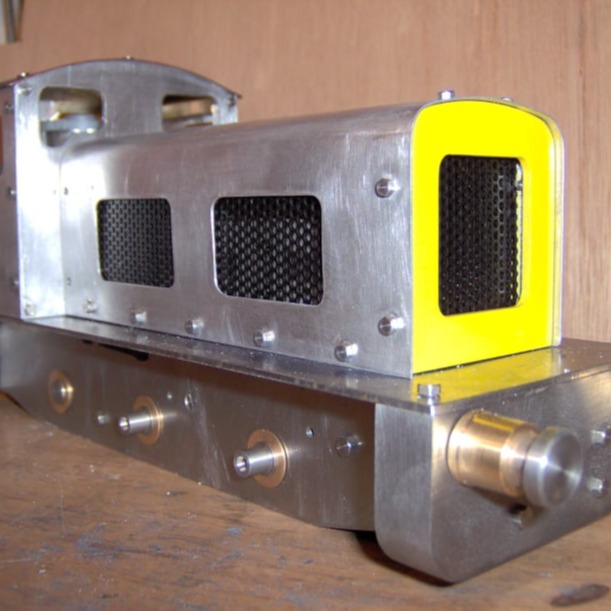
Brass round and square bar was then cut to length to give the formers the required spacing. Finally, 0.5mm aluminium sheet was then cut and bent over the formers to give the overall shape.
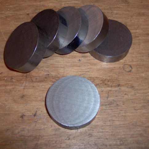
The wheels were made from a 1 3/4" Bright Mild Steel bar.
A longer text about machining wheels is given here.
First the bar was cut into 12mm slices
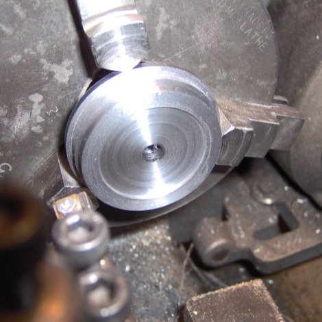
Each slice was mounted in the chuck and the rim and tread of the wheel were turned just over sized and leaving both at 90º to each other.
The centre hole was centre drilled, drilled and reamed to match the axles.
Finally a recess was machined in the face of each wheel. This was all done in one setting in the chuck to ensure concentricity.
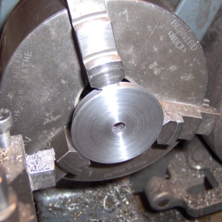
Next each wheel was reversed in the chuck and held by the 90º shoulder previously machined. Then the back was turned to get the wheel to the final thickness (6mm).
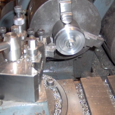
To finish the wheels to final size, an arbor equal to the size of the axle was turned and threaded to take a nut.
The top slide was set over to 3º to cut the tread taper and the tool post turned so that the edge of the tool would cut the 10º taper needed on the flange.
Then each wheel was mounted on the arbor and skimmed to the final size.
Finally wheels were fitted to the arbor with the rear face outwards and the 10º taper was added to this side of the rim.
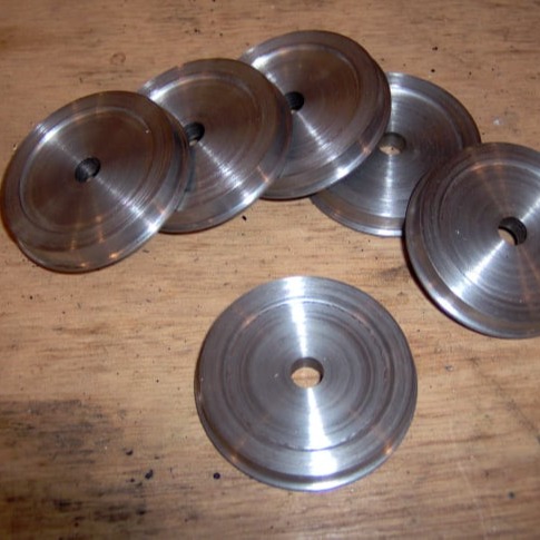
The 6 wheels with matching profiles completed
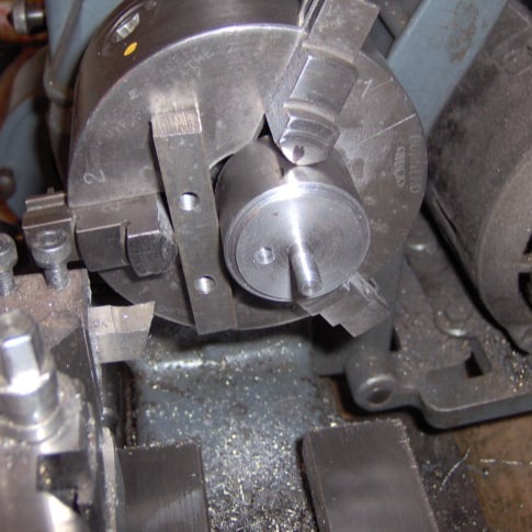
To drill the crank pin holes the same wheel arbor was used but it was mounted 'off-centre' in the lathe. This could be done using the 4 jaw chuck or as shown here using a suitable piece of packing in the 3 jaw.
A clearance hole was drilled in the jig.
Then each wheel was mounted in turn and the crank pin hole was centre drilled, drilled and reamed to final size.
All the wheels were machined in one setting to ensure all the pins were on the dame radius from the axle.
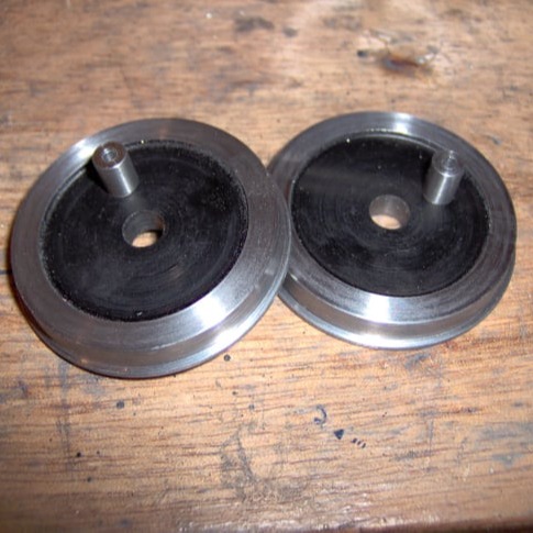
The wheels were painted before the crank pins were glued in place using Loctite.
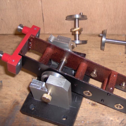
To quarter the wheels a simple jig was made up out of 3 pieces of 12mm aluminium plate and some brass thumb screws. The distance between the vertical plates was adjustable, to allow for different gauges. The thumb screws had a point on the end to locate in the axle centres.
The wheels were secured to the shafts with Loctite. The frame had to be included in this assembly, as there were no horn-blocks in this design.
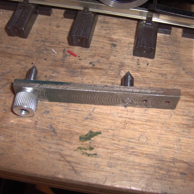
To ensure that the holes in the coupling rods were equal to the axle spacing, a simple jig was used to copy the axle positions onto the blank steel plate. The jig was simply a strip of steel with a fixed pin, which would locate in one axle centre. The second pin was placed in an oversized hole so that it could be moved slightly and it was held in place by a knurled nut.
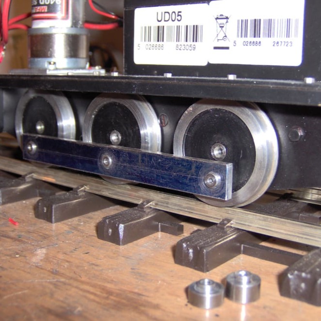
The coupling rods themselves were made from 3/16" steel plate. Once the holes had been marked out, they were drilled to size and tested for a running fit on the loco.
The holes had to be opened out slightly to get a nice running fit.
Finally the rods were shaped using some heat-treated filing buttons cut from silver steel and a file.
This photograph shows the finished coupling rods on test.

Website Software